www.tridonic.com
7
Subject to change without notice. Information provided without guarantee.
Data sheet 10/20-EM090-8
Emergency lighting units
EM converterLED
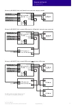
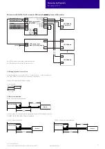
EM converterLED SELFTEST with a standard LED Driver and parallel operation of LED modules
Neutral
+
+
–
–
+
–
–
+
P
O
L
N
Test
switch
Indicator
LED
Control gear
LED
LED
Control gear
Battery
Battery
LED Module
Emergency
–
+
–
+
LED Module
–
+
LED Module
LED control gear
max. 150 W in operation
Switched Line in
L
out
L
in
N
Rest
Rest
L
Neutral
Rest mode control
Rest mode control
Un-Switched Line
Switched Line out
EM ConverterLED
SELFTEST
One LED module is operated in emergency mode.
All LED modules are operated in mains mode.
8 – 9 mm
wire preparation:
0.5 – 1.5 mm²
3.2 Wiring type and cross section
Solid wire with a cross section of 0.5 – 1.5 mm². Strip 8 – 9 mm of insulation
from the cables to ensure perfect operation of terminals.
Wiring: LED module/LED Driver/supply
3.3 Battery connection
LiFePO
4
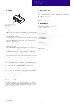
: Direct connection
NiMH: Connection with extension
When using an EM converterLED in combination with a NiMH battery, order the
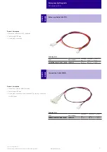
CONNECTION CABLE NiMH 500mm seperately.
LiFePO
4
: Connection with extension
Battery
300
EM converterLED
Battery
500
300
EM converterLED
Battery
500
300
EM converterLED


