www.tridonic.com
11
Subject to change without notice. Information provided without guarantee.
Data sheet 10/20-EM090-8
Emergency lighting units
EM converterLED
6.3 Commissioning
After installation of the luminaire and initial connection of the mains supply
and battery supply to the EM converterLED the unit will commence charging
the batteries for the initial charge time. The recharge occurs also if a new
battery is connected or the module exits the rest mode condition.
The following automatic commissioning duration test is only performed when
a battery is replaced and fully charged.
6.4 Testing
Commissioning test
A full commissioning test is carried out automatically after permanent con-
nection of the supply for 5 days. The easy commissioning feature will set the
initial test day and time to ensure random testing of units.
Functional test
Functional tests are carried out for 5 seconds on a weekly basis under the
control of the Micro controller. Initiation and timing of these tests is set duri-
ng the commissioning of the luminaire.
Duration test
A full duration test is carried out yearly to check the capacity of the batteries.
For a full description of commissioning and test features please refer to
application notes.
Test switch
An optional test switch can be wired to each EM converterLED. This can be
used to to:
• Initiate a 5 seconds function test:
press 200 ms < T < 1 s
• Execute function test as long as switch pressed: press > 1 s
• Reset selftest timer (adjust local timing):
press > 10 s
Timer reset functionality
The timer for function and duration test can be set to a particular time of the
day by either pressing the test switch for longer than 10 seconds or cycling
the unswitched line supply 5 times within 1 minute. The timer adjustment
will enable the test start time to be defined manually at time in day when
the timer was reset. It will also disable the adaptive test algorithm thereby
forcing the unit to perform the test at the same time rather than it being
defined by the adaptive algorithm. This function will only work provided the
interval time is greater than zero (automatic test mode enabled). The delay
timer value set when the unit was commissioned will be reloaded in order to
randomise the tests between adjacent units.
5.4 LED Driver compatibility
The EM converterLED emergency unit use 3 pole technology and is compa-
tible with most LED Drivers on the market, however it is important to check
that the rating of the LED Driver does not exceed the values specified below:
• The max. allowed output current rating of the associated LED Driver is
2.4 A peak (current rating of switching relays of EM converterLED)
• The max. allowed inrush current rating of the associated LED Driver is
60 A peak for 1 ms or 84 A for 255 μs (inrush current rating of switching
relay of EM converterLED)
• The max. allowed output voltage of the associated LED Driver applied to
the EM converterLED output is 450V (voltage withstand between adja-
cent contact of the single switching relay of the EM converterLED)
• The max. allowed LED load of the associated LED Driver is 150 W in
operation. The load must be an LED module.
Check compatibility with the carried out function test (duration at least 5
seconds) individually for each device.
6. Functions
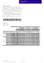
6.1 Duration link selection
Emergency lighting LED Driver supplied with duration link in 3 hours positi-
on (position A).
The position of the link will only be read on first power up. If it is changed
afterwards both the battery and mains supply must be disconnected for 10
seconds to enable the EM converterLED to read the new link position on
reconnection of the battery and mains. It will lead to a false battery failure
indication if the link is changed after installation without this reset.
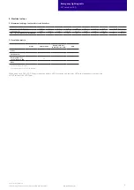
6.2 Status indication
System status is indicated by a bi-colour LED.
LED indication
Status
Comment
Permanent green
System OK
AC mode
Fast flashing green
(0,1 sec on – 0,1 sec off)
Function test
underway
Slow flashing green
(1 sec on – 1 sec off)
Duration test
underway
Red LED on
Load failure
Open circuit / Short circuit / LED failure
Slow flashing red
(1 sec on – 1 sec off)
Battery failure
Battery failed the duration test or function
test / Battery is defect or deep discharged/
Incorrect battery voltage
Fast flashing red
(0,1 sec on – 0,1 sec off)
Charging failure
Incorrect charging current
Double pulsing green
Inhibit mode
Switching into inhibit mode via controller
Green and red off
DC mode
Battery operation (emergency mode)
2 hr
3 hr
No duration link
Position A
Duration
Link position
1 hr
Position B


