


www.tridonic.com
14
Subject to change without notice. Information provided without guarantee.
Data sheet 10/20-EM090-8
Emergency lighting units
EM converterLED
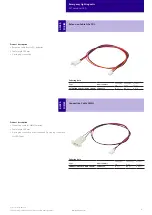
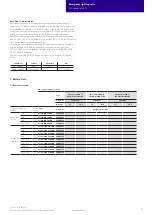
7.3 Accu-NiMh
Capacity 4.0 Ah
International designation
HRMU 19/90
Battery voltage/cell
1.2 V
Cell type
LA
Case temperature range
to ensure 4 years design life
+5 °C to +50 °C
Max. short term temperature (reduced life-time)
70 °C
Max. number discharge cycles
4 cycles per year plus
30 cycles during
comissioning
Max. storage time
12 months
at +5 °C to +25 °C
7.4 Accu-LiFePO4
Capacity 1.5 Ah
International designation
IFpR 19/66
Battery voltage/cell
3.2 V
Cell type
18650
Case temperature range to ensure
4 years design life
+5 °C to +55 °C
6 years design life
+5 °C to +45 °C
8 years design life
+5 °C to +35 °C
Max. short term temperature (reduced life-time)
70 °C
Max. number discharge cycles
50 cycles total
Max. storage time
12 months
at +5 °C to +25 °C
Only use Tridonic batteries.
Comply with UN 38.3 and IEC 62133 (safety testing) protected against over
charge, over discharge, charging at excessive temperatures, short-circuit and
over current.
7.6 Storage, installation and commissioning
Relevant information about storage conditions, installation and commissioning
are provided in the battery datasheets.
Activating NiMH batteries:
In order to activate new batteries, 2-3 full charge-discharge cycles could be
needed. This activating process is defined by charging (24 h) and discharging
(1/2/3 h) of the batteries. If the first duration test fails, please repeat the test
after a 24 hour charging period.
8. Miscellaneous
8.1 Maximum number of switching cycles
EM converterLEDs are tested with 50,000 mains switching cycles of the
associated LED driver.
8.2 Battery replacement
After a battery replacement and a subsequent full charge cycle (24 h) a
duration test is mandatory to prove that with the new battery the rated
duration is achieved.
8.3 Additional information
Additional technical information at www.tridonic.com
→
Technical Data
Guarantee conditions at www.tridonic.com
→
Services
Life-time declarations are informative and represent no warranty claim.
No warranty if device was opened.
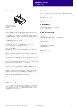
7.5 Safety
7.5.1 Deep discharge protection
When the battery remains connected without charging for a long period of time
after the battery cut off of the driver the battery voltage can still drop. To make
sure the cells are not damaged by this voltage drop, the battery protection
prevents the battery from further discharge below 2.0 V.
7.5.2 Overcharge protection
If in case of an error or the use of a wrong driver the battery gets overcharged
the battery protection will disconnect the battery from the driver at a voltage of
3.9 V. A discharge of the battery is still possible after the protection circuit was
triggered to guarantee emergency operation.
7.5.3 Short-circuit protection
In case of a short circuit the battery protection opens the connection to the
driver and the output is therefore free of voltage. The output will be reactivated
again when the short circuit is removed.
7.5.4 Overtemperature protection
The battery is protected against temporary thermal overheating. If the tempera-
ture limit is exceeded the further charging of the battery is no longer possible.
The temperature protection is activated below approx. 0 °C and above approx.
+60 °C. The discharging of the battery is still possible to guarantee emergency
operation.


