N-Platform Hardware Installation and Safety Guide
27
• Baud rate: 115.2 Kbps
• Character size: 8 bits
• Parity: None
• Stop Bits: One
• Flow Control: None
To attach the Management Processor connection
Describes how to attach the management processor connection.
1.
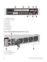
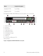
Connect one end of the Category 5 Ethernet cable to the port labeled MGMT (or 10/100 on some
units) located on the front panel.
2.
Connect the other end of the Ethernet cable to your network.
This enables remote management of the system.
To attach network connections
Describes how to attach the network connections.
1.
Attach the cable for incoming traffic to the A port on the segment.
2.
Attach the cable for outgoing traffic to the B port on the segment.
3.
Connect the cables to the appropriate ports on your network router.
Note:
If you are using a TippingPoint Core Controller to distribute network traffic, attach the cables to
the Core Controller 1GbE segment ports. Refer to the Core Controller documentation for more
information.
For more information about TippingPoint 660N/TippingPoint 1400N configuration and network
connections, refer to the
Local Security Manager User's Guide
.
Using the external ZPHA module
The TippingPoint 660N/TippingPoint 1400N can be used with the TippingPoint external ZPHA modular
unit.
Modular ZPHA devices can be daisy-chained together via network cables and the Type A and Type B USB
ports. Refer to the
TippingPoint Modular Copper/Fiber ZPHA Installation Guide
for more information.
Check LEDs
When you connect power to the TippingPoint 660N/TippingPoint 1400N, the system completes a series of
component checks.


