background image


TRAX RetroWave Owner’s Manual


< 13 >


Try setting the ADSR controls to Attack – 0 (fully anti-clockwise), Decay – 6, Sustain – 0, Release – 0. 
 
Play some notes, and the sound will have a envelope reminiscent of a plucked instrument, the sound 
starting abruptly but decaying more slowly, even when the key is held down. 
 
Now turn Sustain up to 2, and play another note – this time, the note stays “on” for as long as the note is 
played, but at a lower audio level. 
 
Turning Release up to 10 will now add another dimension – this time, the note will play as before, but as 
soon as the gate is removed, the sound will die away slowly towards silence. 
 
Try the above again, but with ATTACK set to 5: this time, the sound will build up to maximum volume 
slowly, so that the front edge of the note appears much “softer”. 
 
You can set the ADSR controls to any positions you like to get the sounds you want, but bear in mind 
that 

the DECAY control has no effect if the SUSTAIN control is at the same setting or above.

 Experience 

with the unit will pay dividends, as you learn how to adjust these four parameters for the best effects. 
 
The ADSR contour can also be used to drive the CV inputs of the VCF and VCO. If you turn the 

ADSR 

SWEEP 

control on the VCF clockwise, the positive ADSR output contour will shape the timbre of the 

sound each time a new note is played (you will recognise the sound immediately, as it is one of the most 
used synthesizer effects). Turning the control in the opposite direction will give an inverse contour. You 
may need to adjust the VCF FREQUENCY control to get the best effect. 
 
In the case of the VCO, turning the 

VCO – FM SOURCES - ADSR

 sweep control clockwise will 

introduce a pitch shift each time a new note is played, the most musical sounds being available at the 
lower end of the control. Note that the 

TUNE

 control will need to be adjusted to restore a playable note 

range, especially at high level sweep settings. 
 
Those are the basics that will set you on the road to creating sounds of your own – be sure to read the 
next section to learn more about the RS-1 in detail, and find out how to use the additional features not 
covered in the quick start guide. 


Here we will discuss the RetroWave’s internal modules in depth, so you can learn how they work, and 
how to use them properly to create your own sounds.

 N.B.

 If you are an experienced analogue synth 

user, you can skip this part if you wish, and simply use it as a reference when necessary. 


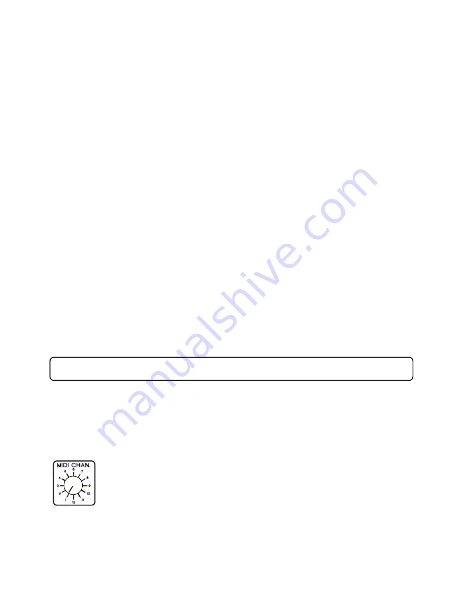
MIDI CHANNEL Selector


Choose from any one of 12 MIDI channels, i.e. the channel that the R-1’s MIDI to CV 
converter will respond to when receiving MIDI information from a connected instrument. 
The RetroWave is a Plug-and-Play machine that does not need to be detected by the 

external equipment, as it only receives MIDI data for conversion to pitch control voltages (CVs), velocity 
and gate signals. 
 
Special thanks go to Trevor Page, for his excellent firmware and MIDI/CV converter design – visit his 
web site at 

www.9090project.co.uk


The Sections in Detail 

Summary of Contents for RetroWave R-1

Page 1: ...TRAX RetroWave R 1 MIDI Controlled Analogue Synthesizer Owner s Manual ...

Page 2: ...TRAX RetroWave Owner s Manual 2 ...

Page 3: ...nit has been dropped Do not open the case of the R 1 or attempt to repair the unit there are no user serviceable parts inside Opening up the unit may invalidate the guarantee Please refer all servicing to Trax Controls who offer after sales service at reasonable rates see the Guarantee and Service Information page Do not place any objects filled with liquids such as vases on the apparatus Do not i...

Page 4: ...Channel Your Creativity Making it Musical The Magic of Modulation Playing With Pulse Width Filter Free for All Got Auto Wah if You Want It Noisy Noodling Random Musings Envelopes and Such The Sections in Detail 13 MIDI CHANNEL Selector GLIDE Control LFO 1 and LFO 2 Low Frequency Oscillators Voltage Controlled Oscillator VCO Voltage Controlled Filter VCF ADSR Voltage Controlled Amplifier VCA Rear P...

Page 5: ...e strange powerful exotic comical and beautiful noises these fantastic new machines were capable of Analogue Versus Digital Digital synths and computer music programs have many advantages modern keyboards can produce unique sounds that are impossible to obtain using analogue technology and software emulations can recreate the majority of classic analogue synth sounds However many musicians are dis...

Page 6: ...nerate dc voltages and or ac signals used to control the operating characteristics of the previous two circuit types An example of a controller is a MIDI to CV converter which translates the digital data sent by MIDI musical instruments sequencers etc into variable voltages that are used to control the frequency of a Voltage Controlled Oscillator or the cutoff frequency of a Voltage Controlled Fil...

Page 7: ...equipment this can be achieved by using the rear panel input jack sockets and some optional extra jack leads The RetroWave also sends out these signals from its internal MIDI CV converter the gate level is 5V so an external synth can receive them and play along in unison or harmony A Word About Your Ears As the RetroWave is capable of producing some loud and occasionally unpredictable noises we re...

Page 8: ...ently damage the R 1 and or the adapter Remember to unplug the power adapter if the unit is not in use for long periods The adapter will get warm when plugged into the mains supply even when the R 1 is switched off this is normal Amplifier and Speaker The AUDIO OUT socket should be connected to the line level input of a PA or instrument amplifier via the supplied jack to jack lead The unit can als...

Page 9: ...o a MIDI signal that the R 1 can use They are available at reasonable cost from online suppliers such as Amazon Make sure that the converter lead has been recognised by the computer BEFORE starting the computer program otherwise no MIDI signals will be sent to the R 1 The RetroWave itself does not require any drivers to be installed and does not need to be recognized by the computer as it is only ...

Page 10: ...ory tone generator N B if the level of signal is too low and your amplifier s volume control is fairly well advanced you can turn up the O P LEVEL control to increase it Making it Musical Now let s try changing the frequency of the tone play a few notes and you will hear the VCO pitch respond in a musical way i e you can play a tune albeit a rather dull sounding one You should also be able to shif...

Page 11: ...u to mix the various waveforms in varying proportions for even stranger special effects Try changing the VCO waveform with the W FORM switch you can then compare and contrast the sound of each You can see detailed descriptions of these four wave shapes in the next section To give some randomness to the notes you play turn up the VCO FM SOURCES SAMPLE HOLD control Note how the pitch range of random...

Page 12: ...O more details can be found in the Voltage Controlled Filter section later Turning RESONANCE down towards minimum will make the sound subjectively louder and more boomy This setting has many uses especially where a sound needs to have plenty of body and substance such as a killer bass line Noisy Noodling In addition to the VCO there is another signal source available white noise Turn down the VCO ...

Page 13: ...ed synthesizer effects Turning the control in the opposite direction will give an inverse contour You may need to adjust the VCF FREQUENCY control to get the best effect In the case of the VCO turning the VCO FM SOURCES ADSR sweep control clockwise will introduce a pitch shift each time a new note is played the most musical sounds being available at the lower end of the control Note that the TUNE ...

Page 14: ...g effect Note that GLIDE facility is only available when using the MIDI to CV converter as it is an integral part of that module s circuit LFO 1 and LFO 2 Low Frequency Oscillators These two sections are identical they do not produce any directly audible tones but between them supply continuous waveforms that are used for modulation and triggering of other sections Both LFO 1 and LFO 2 are used to...

Page 15: ...The SHAPE control at centre position gives equal durations for each of the two tones Thin pulses are obtained by turning the SHAPE control to the anti clockwise position The mark is much shorter than the space of each cycle to give a short high frequency blip and a longer low frequency tone from the VCO At the opposite extreme we have long mark and short space portions of the waveform giving a lon...

Page 16: ... wave to a thin pulse using the MAN shape control When the waveform is at or around 1 1 mark space ratio i e both half cycles are of equal duration the sound is reminiscent of a clarinet when the waveform is changed to a narrow pulse space greater than mark its timbre becomes buzzy The wave shape can be varied manually while playing or automatically by the Low Frequency Oscillator LFO 2 and or the...

Page 17: ...t effect MIDI CV Routing Switch This allows you to send the MIDI CV to the VCO alone upper position the VCO and the VCF together lower position or to neither centre off position The latter is useful if you wish to send external control voltages to the VCO and VCF without the MIDI CV offsetting the VCO pitch and VCF cutoff frequency FM Sources These controls all of which can be freely mixed determi...

Page 18: ... that when this control is set at or near maximum and the manual shape control is near one extreme or the other dropouts in the signal can occur as the square wave is pushed out of its normal pulse width range by the control signal This is not a fault and can indeed be useful for creating some unusual sounds ADSR applies the Attack Decay Sustain Release waveform giving a one shot variation to the ...

Page 19: ... is much higher than that produced by the VCO so take care if using headphones Now let s deal with the audio mixer This combines the outputs of five signal sources the VCO SUB OCTAVE I SUB OCTAVE II NOISE and an external audio input there is no level control for external signals VCO The selected VCO waveform is applied to a level control for mixing with the other signals in any proportion you wish...

Page 20: ...in varying amounts to the filter With the Resonance control set near to oscillation point and a low frequency triangle selected auto wah is produced Rapid bubbling effects are obtained when a high frequency is applied Square waves give a choppy modulation that can be used for special effects When the Resonance control is near its fully anti clockwise position the effect is similar to amplitude mod...

Page 21: ...vel and is not affected by the setting of the range switch Use the Low range for shorter sounds like snare drums electronic blips organs machine gun fire etc and the High range for sounds with longer decay times such as pianos thunderclaps drones etc The Trig Mode switch lets you choose between Normal triggering by MIDI gate or external source and LFO1 Repeat which as its name suggests enables the...

Page 22: ...his input connects directly to the VCO s control voltage input and is scaled at 1V per octave Typically you would use this input to control VCO frequency from an external sequencer older synth or other control voltage source instead of or in addition to MIDI control VCO PWM Applying an external signal here will alter the pulse width of the square wave output VCF CV An external signal applied here ...

Page 23: ...on the MAN shape control If so set the control to the centre position The VCO is not staying in tune Always allow a few minutes after switching on before using the machine on recordings at gigs etc to allow the VCO to temperature to stabilize This will ensure that the machine stays in tune Check also that an LFO is not modulating the VCO if so turn LFO 1 and LFO 2 controls in the VCO FM SOURCES se...

Page 24: ...4 Scan these and print them out then mark the control settings and assign a name for each sound you wish to keep a record of Patch Name _________________________________ Patch Name _________________________________ Blank Patch Sheets ...

Page 25: ... has been taken to ensure that this manual is free from error responsibility cannot be accepted for any incorrect information given Trax Controls cannot be held responsible for any damages either physical or financial brought about by the failure of this product or the inability to use this product We reserve the right to change specifications descriptions terms etc at any time without prior notic...

Page 26: ...TRAX RetroWave Owner s Manual 26 System Block Diagram ...

Reviews: