P a g e
|
31
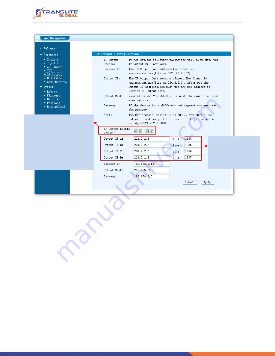
Figure-8
Modulator Setting
Enter in
“Modulator” and it will display the Modulator Configuration screen as Figure-9 where
can set modulation parameters.
RF On
–To decide whether to enable the RF (carrier A/B/C/D) output or not.
RF Frequency A/B/C/D
– to set the RF frequency for the 4 carriers
RF Out level
–to set the RF output level
ASI Output
– To select carrier output channel for ASI output (Output A: The ASI output
programs are same as carrier A; Output B: The ASI output programs are same as carrier B; and
the like.)
This device is with MPTS IP
output. The 4 boxes represent
respectively IP Channel
1/2/3/4. Click the related
box(es) to enable the
corresponding channel(s) to
output programs.
To configure the
output IP address
and
ports
for the 4 IP
Channels respectively.
Summary of Contents for TL-9542A
Page 6: ...P a g e 6 1 4 PRINCIPLE CHART...
Page 13: ...P a g e 13 3 1 LCD MENU STRUCTURE...
Page 41: ...P a g e 41...


