background image

P a g e

 | 

28 


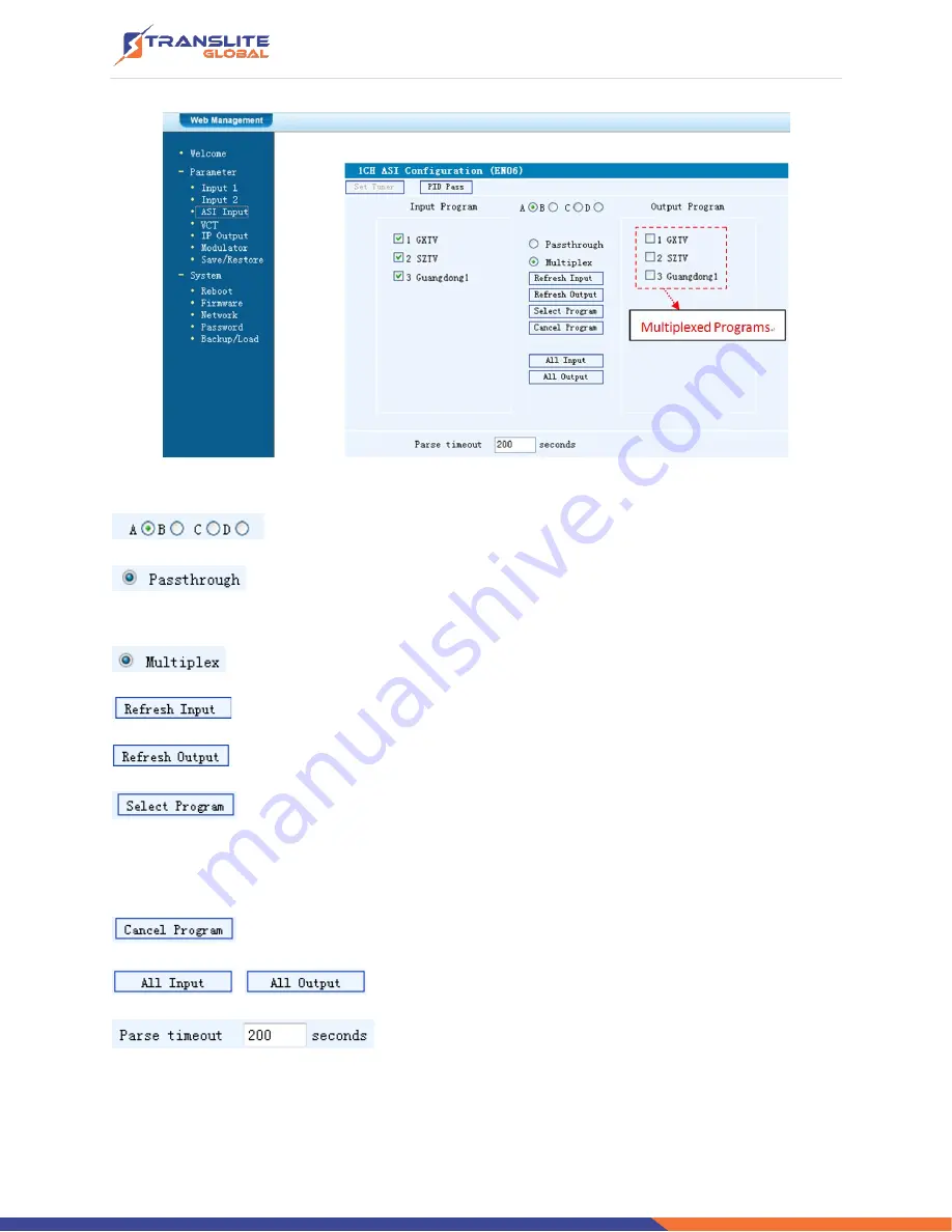
Figure-5 


Select the carrier output channel for the multiplexed programs.  

If this item is selected, all the input programs will pass through without any 

elimination. 

 Selecting this item to allow user select programs as required to output. 

 Click 

“Refresh Input” to refresh the input program list. 

 Click 

“Refresh Output” to refresh the output program list. 

 When user checks one input program with 

“√”, one can transfer the checked 

program to the right box to output. 

Here user can select the programs which we want to output or we can output all the programs. 

 Similarly, user can cancel the multiplexed programs from the right box. 

&

to select all the input/output programs with one-time clicking. 

Time limitation to parse the input programs 

Summary of Contents for TL-9542A

Page 1: ...gn and manufacturing TRANSLITE GLOBAL LLC shall have no liability for any error or damage of any kind resulting from the use of this document COPY WARNING This document includes some confidential info...

Page 2: ...2 1 GENERAL PRECAUTIONS 10 2 2 POWER PRECAUTIONS 10 2 3 DEVICE S INSTALLATION FLOW CHART ILLUSTRATED AS FOLLOWING 10 2 4 ENVIRONMENT REQUIREMENT 11 2 5 GROUNDING REQUIREMENT 11 CHAPTER 3 OPERATION 12...

Page 3: ...ould be from satellite receivers closed circuit television cameras Blue ray players and antenna etc Its output signals are to be received by TVs STB etc with corresponding standard With its various in...

Page 4: ...Video Encoding MPEG2 MPEG4 AVC H 264 Input HDMI 4 or SDI 4 Resolution 1920 1080_60P 1920 1080_50P for MPEG4 AVC H 264 only 1920 1080_60i 1920 1080_50i 1280 720_60p 1280 720_50P 720 480_60i 720 576_50i...

Page 5: ...ep Constellation 8VSB SYSTEM Local interface LCD control buttons Remote management Web NMS output ASI out BNC type 1 IP 4 SPTS or 1 MPTS out over DUP RTP RTSP RJ45 100M NMS interface RJ45 100M Languag...

Page 6: ...P a g e 6 1 4 PRINCIPLE CHART...

Page 7: ...output for single ATSC T carrier is only around 19 Mbps 11Mbps x 4 44Mbps 19 x 2 Mbps It means the single or even dual ATSC T carriers simply can t carry the 4 channels 1080i HD program if the average...

Page 8: ...Panel Illustration 1 2 3 4 5 6 7 8 9 1 LCD Screen 2 NMS Port 3 Data Port 4 Power and Alarm Indicators 5 TS Lock Indicators 6 Up and Down Left and Right Buttons 7 Enter Mode For Confirm 8 Menu Button...

Page 9: ...output port 5 ASI input port 6 ASI output ports 7 Switch 8 Power supply slot 9 Grounding CHAPTER 2 INSTALLATION GUIDE This section is to explain the cautions the users must know in some case that pos...

Page 10: ...ers 2 2 POWER PRECAUTIONS When you connect the power source make sure if it may cause overload Avoid operating on a wet floor in the open Make sure the extension cable is in good condition Make sure t...

Page 11: ...05KPa Door Window Installing rubber strip for sealing door gaps and dual level glasses for window Wall It can be covered with wallpaper or brightness less paint Fire Protection Fire alarm system and e...

Page 12: ...ace and the equipment can be conveniently operated and managed by user according to the procedures displayed on the LCD Keyboard Function Description MENU Cancel current entered value resume previous...

Page 13: ...P a g e 13 3 1 LCD MENU STRUCTURE...

Page 14: ...P a g e 14 Initial Status Switch on the device and after a few seconds initialization it presents start up pictures as below...

Page 15: ...2 GENERAL SETTINGS FOR MAIN MENU By pressing Lock key on the front panel user can enter the main menu The LCD will display the following pages User can press UP DOWN buttons to specify menu item and...

Page 16: ...HDMI encoding module supports both MPEG2 and H 264 MPEG 4 AVC H 264 formats Move the triangle mark with LEFT RIGHT keys to specify the intended format and press ENTER to confirm Video Bit Rate Move t...

Page 17: ...m is for checking the quantity of input programs from the ASI IN port Select Program A is for selecting programs from the ASI IN to output through Carrier A Move the triangle mark to specify the progr...

Page 18: ...ATSC Modulating is with 4 carrier outputs 3 1 3 4 represent the Carrier A Carrier B Carrier C and Carrier D respectively User can enter 3 1 3 2 3 4 3 4 to set the corresponding modulating parameters...

Page 19: ...om 30 10dbm 81 97db V with 0 1db step After entering this setting submenu user can shift UP DOWN LEFT RIGHT key to set the output level and press ENTER to confirm RF On This interface is to decide whe...

Page 20: ...are same as carrier output C Output D the ASI output programs are same as carrier output D 4 IP Output Setting TL 9542A encoder modulator ATSC Modulating is with 4 MPTS IP output Output A B C and D 4...

Page 21: ...etwork setting After enter Network Setting there are three submenus shows as the following LCD displays User can press UP DOWN to choose this item and ENTER LEFT RIGHT to set the parameters 5 5 Reset...

Page 22: ...menu user can press UP DWON key to select and repress ENTER to confirm User can restore the device into the last saved configuration by choosing 7 1 and restore the device into factory configuration b...

Page 23: ...buttons for setting configuration but also can control and set the configuration in computer by connecting the device to web NMS Port User should ensure that the computer s IP address is different fro...

Page 24: ...ss is 192 168 99 252 we then change the device IP to 192 168 99 xxx xxx can be 0 to 255 except 252 to avoid IP conflict Use web browser to connect the device with PC by inputting the Encoder Modulator...

Page 25: ...enter the corresponding interface to check information or set the parameters It automatically identifies and displays the signal source interface and real time encoding bit rate of corresponding inpu...

Page 26: ...rn to red This column is for setting the 1st HDMI IN program This column is for setting the 2ed HDMI IN program The 4 boxes respectively represent IP Channel A B C and D The related programs can outpu...

Page 27: ...e modified parameters Input 2 Similarly from the menu on left side of the webpage clicking Input 2 it displays the information of the 2 programs from the 2nd HDMI encoding slot Figure 4 ASI Input Clic...

Page 28: ...to refresh the input program list Click Refresh Output to refresh the output program list When user checks one input program with one can transfer the checked program to the right box to output Here...

Page 29: ...nd so on which user just wants to pass them through the multiplexing module without changing anything This is the main purpose of this function Click Add to add more boxes for filling the Input Output...

Page 30: ...s Figure 7 Click Add to add boxes where to configure parameters in its respective fields After setting all the data users need to click Save to save the setting IP Output Click IP Output from the left...

Page 31: ...4 carriers RF Out level to set the RF output level ASI Output To select carrier output channel for ASI output Output A The ASI output programs are same as carrier A Output B The ASI output programs ar...

Page 32: ...enu it will display the screen as Figure 10 where can save the configuration permanently to the device Click Save Configuration for store the data permanently to the device By using Restore Configurat...

Page 33: ...atically Figure 11 Update the Device Click Firmware from the menu it will display the screen as Figure 12 Here user can update the device by using the update file Click Browse to find the path of the...

Page 34: ...4 Figure 12 Network When user clicks Network it will display the screen as Figure 13 It displays the network information of the device Here user can change the device network configuration as needed F...

Page 35: ...Figure 14 Keyboard and LCD Lock If it is marked with the LCD and keyboard will be locked to avoid unrelated users modifying or view the device information and configurations User can t operate the ke...

Page 36: ...o load the backup file to the device Figure 15 CHAPTER 5 TROUBLESHOOTING All TRANSLITE products have been passed the testing and inspection before shipping out from factory The testing and inspection...

Page 37: ...s necessary Checking all signal cables have been properly connected Frequently switching on off device is prohibited the interval between every switching on off must greater than 10 seconds Conditions...

Page 38: ...P a g e 38 CHAPTER 7 APPLICATIONS 1 Residences and Private Homes Video content DVB T ISDB T distribution 2 Outside Audio Video contents ON AIR DVB T ISDB T distribution...

Page 39: ...P a g e 39 3 Hotel Audio Video contents DVB T ISDB T distribution 4 Bar Audio Video contents distribution 5 Cinema Audio Video contents DVB T ISDB T distribution...

Page 40: ...ing with 1 or dual SDI in DVB S2 C ISDB ATSC tuner input YPbPr HDMI CVBS input MPEG2 SD YPbPr S Video CVBS input MPEG4 AVC H 264 encoding with 1 or 2 HDMI input MPEG2 HD encoding with 1 or 2 HDMI inpu...

Page 41: ...P a g e 41...

Reviews: