background image

Programmable  displays  with  a  wide  se-

lection of inputs and outputs for display of temperature, 
volume  and  weight,  etc.  Feature  linearisation,  scaling, 
and  difference  measurement  functions  for  programming 
via PReset software.

Interfaces  for  analogue  and  digital 

signals as well as HART

®

 signals between sensors / I/P

converters / frequency signals and control systems in Ex 
zone 0, 1 & 2 and for some modules in zone 20, 21 & 22.

Galvanic isolators for analogue and digital 

signals as well as HART

®

 signals. A wide product range 

with both loop-powered and universal isolators featuring 
linearisation, inversion, and scaling of output signals.

PC or front programmable modules with 

universal options for input, output and supply. This range 
offers  a  number  of  advanced  features  such  as  process 
calibration, linearisation and auto-diagnosis.

A  wide  selection  of  transmitters  for  DIN 

form  B  mounting  and  DIN  rail  modules  with  analogue 
and digital bus communication ranging from application- 
specific to universal transmitters.

Temperature

Isolation 

Ex interfaces

Universal

Displays

DK

UK

FR

DE

Side 1

Page 35

Page 69

Seite 103

S I G N A L S   T H E   B E S T
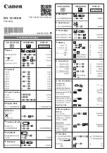
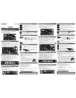
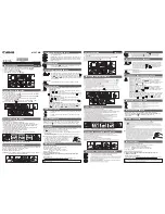
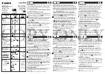
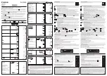
2 2 8 9

S i g n a l   C a l c u l a t o r

N o .   2 2 8 9 V 1 0 1 - I N   ( 1 0 1 5 )
F r o m   s e r .   n o .   9 8 0 3 3 8 0 0 1

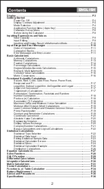
Summary of Contents for 2289

Page 1: ...oth loop powered and universal isolators featuring linearisation inversion and scaling of output signals PC or front programmable modules with universal options for input output and supply This range offers a number of advanced features such as process calibration linearisation and auto diagnosis A wide selection of transmitters for DIN form B mounting and DIN rail modules with analogue and digita...

Page 2: ...er 39 Signal limiter 39 Averaging transmitter 39 Slope transmitter dI dt function 39 Analogue multiplexer 40 Inputs 40 Digital input 2289A 40 Output 40 Electrical specifications 41 Order 43 Block diagrams 44 Hardware programming 46 Jumper positioning 47 External up down operation of manual controller 47 Routing diagram 48 Programming operating the function keys 50 Function description selection of...

Page 3: ... jumpers can now be moved When assembling the back plate and housing please make sure no wires are stuck 37 DECLARATION OF CONFORMITY As manufacturer PR electronics A S Lerbakken 10 DK 8410 Rønde hereby declares that the following product Type 2289 Name Signal calculator is in conformity with the following directives and standards The EMC Directive 2004 108 EC and later amendments EN 61326 1 For s...

Page 4: ...e of the input over a set period to an analogue output signal The min and max slope to be converted are entered in of the input span The slope can be selected as either positive or negative By means of a pressure transmitter the dI dt function is suitable for for instance leak monitoring or flow measurement of substances with a high viscosity grade 39 SIGNAL CALCULATOR 2289 Two analogue inputs Mul...

Page 5: ... max value Input resistance Nom 50 Ω 41 ANALOGUE MULTIPLEXER At a deactivated digital input input A x P1 is sent to the output At an activated digital input input B x P2 is sent to the output P1 and P2 are scaling factors for the two inputs INPUTS ANALOGUE INPUTS 2289A The A and B inputs can be programmed according to your choice to receive current signals in the range 0 20 mA for instance 4 20 mA...

Page 6: ...P Pull down 0 VDC 6 9 mA Pulse length 50 ms Pt100 input 2289B Measurement range 99 850 C Min measurement range span 50 C Max offset 50 of selec max value Cable resistance per wire max 25 Ω Sensor current Nom 1 25 mA Response time 100 ms Basic accuracy 0 2 C Temperature coefficient span 100 C 0 01 C Camb span 100 C 0 01 of span Camb Immunity influence span 100 C 1 of span span 100 C 0 5 of span Eff...

Page 7: ...BLOCK DIAGRAM 2289B 45 BLOCK DIAGRAM 2289A 44 ...

Page 8: ...AL CONTROLLER Channel A 0 20 mA 0 10 VDC JP4 ON JP4 OFF MENU 2 3 I MENU 2 3 U Channel B 0 20 mA 0 10 VDC JP3 ON JP3 OFF MENU 3 3 I MENU 3 3 U NPN PNP JP6 ON JP6 OFF Output JP1 JP2 JP5 MENU 4 3 0 10 mA 0 20 mA OFF OFF OFF ON 1 2 0 500 mV 0 1000 mV ON OFF OFF ON 3 4 0 5 V 0 10 V OFF ON OFF ON 5 6 ...

Page 9: ...nnel selection Menu 5 1 14 Function Averaging 1 1 Averaging time 1 2 Stack size 1 14 1 3 Channel selection Time constant in s 0 slope in 100 slope in Sampling in s 1000 Sampling in s If no buttons are pressed for a period of 20 minutes the display returns to default 0 0 Fast Setting Fast Setting Store and exit fast setting 040 Enable change in all stages Disable change Routing diagram Function sel...

Page 10: ... max and min Valid selections are 99 999 Factor 51 PROGRAMMING OPERATING THE FUNCTION KEYS DOCUMENTATION FOR ROUTING DIAGRAM GENERAL The programming is menu controlled The main menus are numbered in level 0 X 0 and the submenus are numbered in level 1 X 1 to X 5 Each submenu has an accompanying entry menu The menus are structured in such a way that the menus most frequently used are closer to the ...

Page 11: ... CH Input for subtraction If A has been selected the result is A B If B has been selected the result is B A Possible selections are A or B Input 1 5 HLd Fixing of signal on input A When the digital input is active the input signal is fixed on the value it had when activated Max and Min functions are not available Possible selections are EnA Enable hold or dSA Disable hold 1 6 OOr Input signal less...

Page 12: ...value is entered in of the output span Valid selections are 0 100 Per cent 1 2 IH Maximum output value The maximum output value is entered in of the output span Possible selections are 0 100 Per cent 55 1 2 CH Input Possible selections are A or B Input 1 0 PAr for PID controller Function no 11 1 1 SEt Setpoint The setpoint value is entered in of the input span Valid selections are 0 99 9 Per cent ...

Page 13: ...Valid selections are current 0 0 20 0 mA or voltage 0 0 10 0 VDC For modules with a Pt100 input the valid 0 temperature is 99 850 C 57 1 3 IE Internal external signal limiter When I has been selected the other analogue input is disabled and the signal limiting follows the set IL and IH values When EL has been selected the high limit will follow the set IH value while the low limit will follow the ...

Page 14: ... extra offset of 50 of the output span This means that the signal range starts at 15 mA and starts to limit at 20 mA At most calculations the calculation offset must be set to 0 but at complex calculations it can be used for moving the range of the output signal range 59 2 2 IAH Setting of 100 input signal Valid selections are current 0 0 20 0 mA or voltage 0 0 10 0 VDC For modules with a Pt100 in...

Page 15: ...averaging time has expired the average value is calculated by dividing the memory value by the number of measurements made and the output is then updated by this value The averaging function 61 When calculating scale factors the input and output signal spans always have values between 0 and 1 When adding 2 identically scaled input signals of for instance 4 20 mA the output would be 8 40 mA at the ...

Page 16: ... is updated each time a period dt has expired The slope can be selected as either positive or negative The input signal can be averaged according to an exponential function so that it can be applied to noisy signals Example Minimum slope dIL 0 Maximum slope dIH 1 Period 5 seconds Analogue output 4 20 mA Result Has the input value not been changed within 5 seconds the output will be 4 mA Has the in...

Page 17: ...65 64 ...

Page 18: ...67 66 ...

Reviews: