


HOW TO DISMANTLE SYSTEM 2200
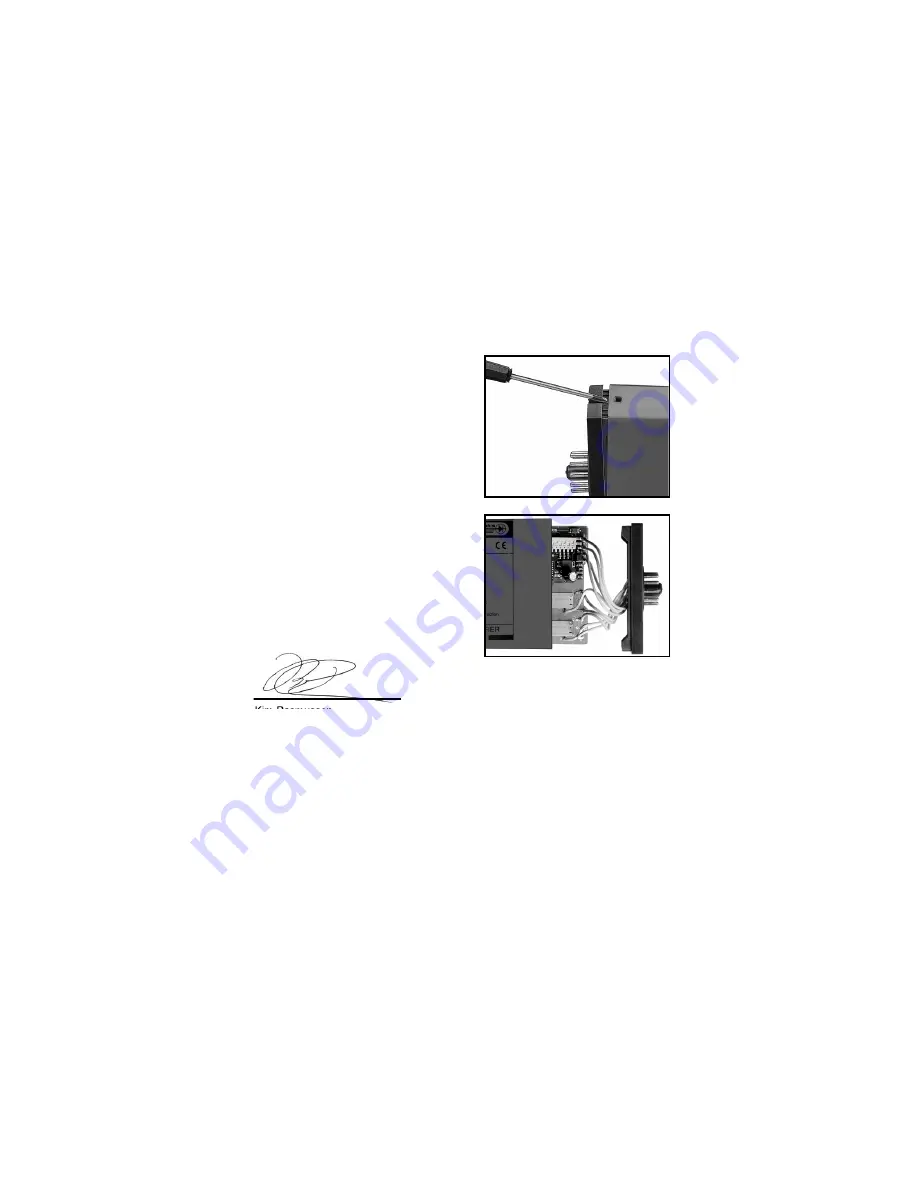
Picture 1:
The back panel of the module is
detached from the housing by way
of a screwdriver.
Picture 2:
After this, the back panel can be
pulled out together with the PCB,
but please notice the position of
the PCB as there is a number of
different positions in the house. Do
not pull the wires unnecessarily,
instead pull the PCB.
Switches and jumpers can now be
moved.
When assembling the back plate
and housing, please make sure no
wires are stuck.
37
DECLARATION OF CONFORMITY
As manufacturer
PR electronics A/S
Lerbakken 10
DK-8410 Rønde
hereby declares that the following product:
Type: 2289
Name: Signal calculator
is in conformity with the following directives and standards:
The EMC Directive 2004/108/EC and later amendments
EN 61326-1
For specification of the acceptable EMC performance level, refer to the
electrical specifications for the module.
Rønde, 5 June 2009
Kim Rasmussen
Manufacturer’s
signature
36
Summary of Contents for 2289
Page 7: ...BLOCK DIAGRAM 2289B 45 BLOCK DIAGRAM 2289A 44 ...
Page 17: ...65 64 ...
Page 18: ...67 66 ...


