49
48
0.0
5.0
5.1
5.2
5.
3
3.0
3.1
3.2
3.
3
4.
3
1.0
2.0
2.1
2.2
2.
3
4.0
4.1
4.2
5.
4
4.
4
5.
1
5.
0
A
input
B
input
Output
1.3
1.4
1.5
1.6
1.7
1.8
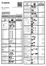
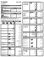
Menu
5.1
=
15
Function:
Slope
transmitter
1.1
1.2
1.3
1.4
1.5
1.0
Parameter
line
1.0
P
arameter
line
M
e
n
u 5
.1 = { 8 , 9 }
Function:
Sample
/ hold
- peak
1.1 - 1.3
N
o
fu
n
c
ti
o
n
1.4 C
h
a
n
n
e
l s
e
le
c
ti
o
n
Menu
5.1
=
10
Function:
T
ime
delay
1.1 T
im
e
c
o
n
s
ta
n
t
1.2 C
h
a
n
n
e
l s
e
le
c
ti
o
n
Integrating
time
Differentiating
time
Setpoint
int.
/ external
Direct
/ inverted
Digital
input
function
Power
UP
M
e
n
u 5
.1 = { 5 , 6 }
Function:
Multiplication
/ division
1.1
Scale
factor
1.2 N
o
function
1.3
Calculation
offset
1.4
Divisor
channel
selection
1.5
Input
A
hold
M
e
n
u 5
.1 = { 1 , 2 , 3 , 4 }
Function:
+,
-,
Max.,
Min.
1.1
Input
A
scale
factor
1.2
Input
B
scale
factor
1.3
Calculation
offset
1.4
Channel
selection
1.5
Input
A
hold
1.6 O
u
t
o
f
range
M
e
n
u 5
.1 = 7
Function:
Root
/ Power
1.1
Scale
factor
1.2
Power
of
function
1.3
Calculation
offset
1.4
Channel
selection
1.5 L
o
w
c
u
t
o
ff
Menu
5.1
=
12
Function:
Man./auto
controller
1.1
Step
up/down
in
%
1.2
Int./external
up/down
1.3
Digital
input
function
Menu
5.1
=
16
Function:
Analogue
multiplexer
1.1
Input
A
scale
factor
1.2
Input
B
scale
factor
Menu
5.1
=
13
Function:
Signal
limiter
1.1
Min.
output
%
1.2
Max.
output
%
1.3
Int./ext.
Lo/
ext.
Hi
1.4
Channel
selection
Menu
5.1
=
14
Function:
A
v
eraging
1.1 A
v
eraging
time
1.2
Stack
size
( 1...14
)
1.3
Channel
selection
T
ime
constant
in
s
0%
slope
in
%
100%
slope
in
%
Sampling
in
s*1000
Sampling
in
s
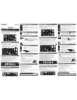
If
no
buttons
are
pressed
for
a
period
of
20
minutes,
the
display
returns
to
default
0.0.
Fast
Setting
Fast
Setting
Store
and
exit
fast
setting
040
=
Enable
change
in
all
stages
- -
-
=
Disable
change
Routing
diagram
Function
selection
V
alue
1...16
See
function
description
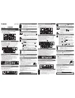
Application
Programming
access
0...999
Input
0%
Input
0%
Output
0%
Output
100%
Input
100%
Input
100%
Password
code
Parameters
Input
A
Input
B
Press
or
for
2
s
for
an
automatic
counting
Decrement
setpoint
Increment
setpoint
Analogue
output
Input
type
U
=
voltage
I
=
current
U
=
voltage
I
=
current
Input
type
Output
type
Frequency
50
Hz
60
Hz
Display
Pt
100:
-99...850
°
C
P
t 100:
-99...850
°
C
Pt
100:
°
C
Pt
100:
No
function
0.0...20.0
mA
0.0...10.0
VDC
0.0...20.0
mA
0.0...10.0
VDC
0.0...20.0
mA
0.0...10.0
VDC
0.0...20.0
mA
0.0...10.0
VDC
0.0...20.0
mA
0.0...10.0
VDC
0.0...20.0
mA
0.0...10.0
VDC
001
=
0...10
mA
002
=
0...20
mA
003
=
0...500
mV
004
=
0...1000
mV
005
=
0...5
V
006
=
0...10
V
Overrange
ON
OFF
Memory
ProgrammingProgramming
Press
and
hold
,
then
press
Press
a
nd
hold
,t
hen
p
ress
to
store
changes
to
store
changes
Change
of
parameter
Change
of
parameter
Next
digit
or
point
Next
digit
or
point
Go
to
entry
menu
/ Leave
Go
to
entry
menu
/Leave
menu
without
changes
menu
without
c
hanges
M
a
in
menus
Menu
5.1
=
11
Function:
PID
controller
1.1
1.2
Setpoint
Proportional
band
Summary of Contents for 2289
Page 7: ...BLOCK DIAGRAM 2289B 45 BLOCK DIAGRAM 2289A 44 ...
Page 17: ...65 64 ...
Page 18: ...67 66 ...