background image


10 

If  the  calibration  was  not  successful,  one  of  the  error  messages  below  will  appear.  Take  the 
indicated action to correct the problem, and then perform a new calibration. 

"Err0" - The calibration test weight or the keyed-in weight is larger than the full capacity of the 
scale. Change the calibration test weight or check the input data. 

"Err1" - The calibration test weight or the keyed-in weight is smaller than 1% of the full capacity 
of the scale. Change the calibration test weight or check the input data. 

"Err2" – There is not enough signal from the load cells to establish a proper calibration. Most 
commons  causes  include  incorrect  load  cell  wiring,  a  mechanical  obstruction  or  a  faulty  load 
cell.  

VIEW CALIBRATION VALUES (F18)  

Note: The values displayed in this procedure are valid only after a successful calibration has been 

performed using F16 and F17. 

1.  While in the Setup mode, scroll to "F 18", then scroll down once using the ZERO key to enter 

View calibration menu. 

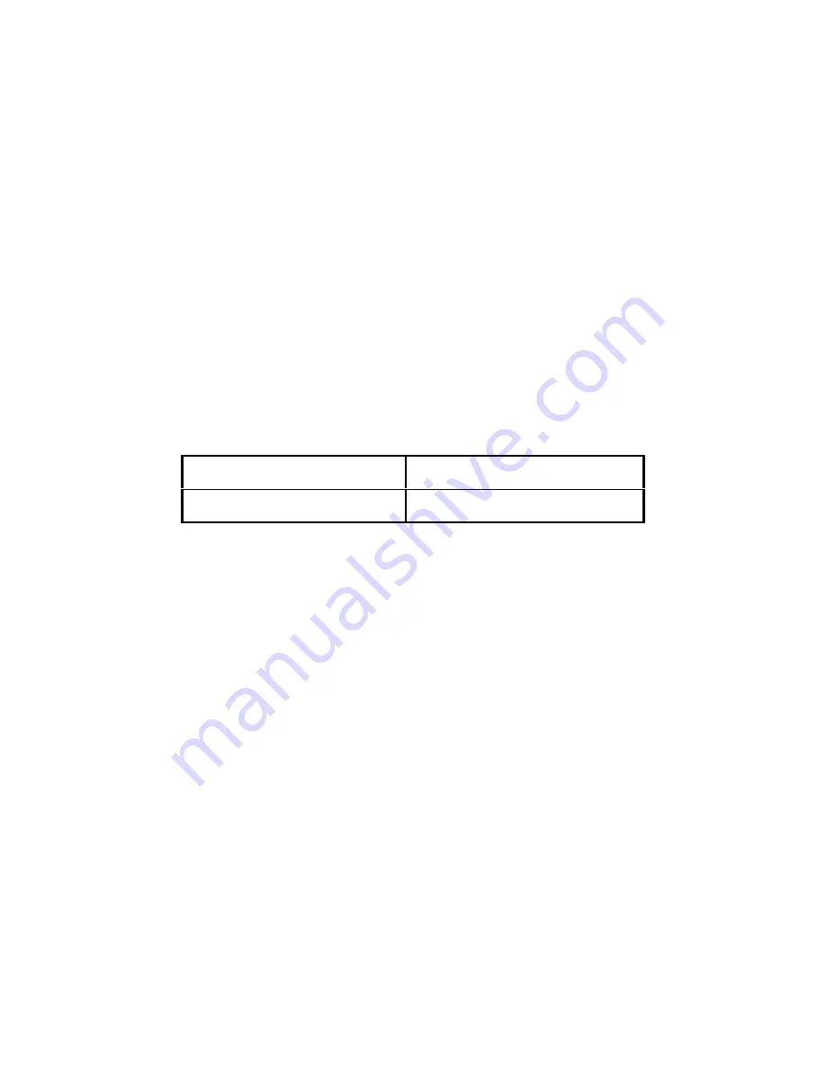
2.  The display will show the information listed in Table 2. The code will display briefly followed by 

the value. It is recommended that you record each value in the table below. Press any key to 
continue down the list. At the completion of the list, the indicator reverts back up to F18.  

ZERO CALIBRATION VALUE (C0) 

SPAN CALIBRATION VALUE (C1) 


Table 2: Calibration Value Table  

KEY-IN ZERO CALIBRATION VALUE (F19)  

Note: This procedure is intended for emergency use only in the case of non-volatile memory loss. 

A  valid  zero  calibration  value,  obtained  from  a  successful  F16  calibration  procedure,  must 
be used. 

1.  While in the Setup mode, scroll to "F 19", and then scroll down once using the ZERO key. The 

display will momentarily show " CAL 0", followed by a value of zero 

2.  Use the four directional keys to enter in the actual zero calibration value. 

3.  After  entering  the  exact value, press the NET/GROSS key to save the value. The display will 

show " E CAL 0" momentarily, and then revert back up to F19.  


KEY-IN SPAN CALIBRATION VALUE (F20)  

Note: This procedure is intended for emergency use only in the case of non-volatile memory loss. 

Valid span calibration values, obtained from a successful F17 calibration procedure, must be 
used. 

1.  While in the Setup mode, scroll to "F 20", and then scroll down once using the ZERO key. The 

display will momentarily show "CAL 1", followed by a flashing zero. 

2.  Use the four directional keys to enter in the actual span calibration value  

3.  After setting the exact value, press the NET/GROSS key to save the value. 

4.  If  the  entered  values  are  entered  successfully,  the  display  will  show  "E  CAL  1"  momentarily 

before reverting back up to F20. 

Summary of Contents for TI-500 Plus

Page 1: ...i TI 500 Plus DIGITAL WEIGHT INDICATOR Setup Operation Manual Revision 1 0 975 Deerfield Parkway Buffalo Grove IL 60089 April 3 2008 Tel 847 419 9180 Fax 847 419 1515 http www transcell net...

Page 2: ...ITEM 14 PIECE COUNTING MODE 14 PEAK HOLD MODE 15 REMOTE DISPLAY MODE 15 LEGAL FOR TRADE SEALING 15 APPENDIX A SPECIFICATIONS 16 APPENDIX B SERIAL PORT INFORMATION 17 SERIAL PORT MODES 17 DEMAND DUPLE...

Page 3: ...ce when the equipment is operated in a commercial environment This equipment generates uses and can radiate radio frequency energy and if not installed and used in accordance with the instructions man...

Page 4: ...er must first be removed to make the appropriate connections to the weigh platform printer remote display and power supply To remove the rear cover simply remove the screws that secure it to the enclo...

Page 5: ...ex RS 232 port designed for connection to a remote display DSUB9 Connector Pin No Wire Name Pin No Wire Name 2 RXD 7 RTS 3 TXD 8 CTS 5 Ground Connection assignments for all serial RS 232 communication...

Page 6: ...r off the indicator 2 Press and hold the SET key for about three seconds while turning the unit back on The display shows F 1 to indicate that you are in Setup Menu mode 3 Use the navigation keys show...

Page 7: ...and environmental limits on the useful system resolution Pressing the ZERO key to scroll down one level begins the sequence Key in 100 50000 5000 NA 3000 F2 Sampling Rate Sets the sampling rate in He...

Page 8: ...es indicator into the span calibration routine Scrolling down with the ZERO key one level begins the procedure Press ZERO key to begin sequence F18 View Calibration Actuates the function that allows y...

Page 9: ...25d US 0 5d F34 Auto Print Min Weight Selects the minimum weight at which the auto print function will work if enabled Selections are in display divisions d Scrolling down with the ZERO key one level...

Page 10: ...l digit segments decimal points and LCD annunciators in a test sequence Press ZERO key to begin sequence A6 Output String Selects fixed output string for serial port Standard Chipset only Refer to App...

Page 11: ...ease the flashing digit by pressing the UNITS key Decrease the flashing digit by pressing the ZERO key Pressing the PRINT key or the TARE key will change the position of the flashing digit USER MODE K...

Page 12: ...key to enter zero calibration menu The display will momentarily show C 0 followed by a value This value is the internal A D count and can prove useful when trying to troubleshoot setup problems 2 Afte...

Page 13: ...or check the input data Err2 There is not enough signal from the load cells to establish a proper calibration Most commons causes include incorrect load cell wiring a mechanical obstruction or a fault...

Page 14: ...span calibration values obtained from a successful F17 calibration procedure must be used 1 While in the Setup mode scroll to F 20 and then scroll down once using the ZERO key The indicator will prom...

Page 15: ...dicator is displaying net weight G Indicates that the indicator is displaying gross weight T Indicates that a tare weight has been established in the system lb kg Indicates the unit of the displayed w...

Page 16: ...If necessary press the ZERO key to obtain a weight reading of zero 3 If weighing an item in a container place the empty container on the scale s platter and after allowing the weight indication to sta...

Page 17: ...for your scale to process accurately 5 To exit the piece count mode press the UNITS key NOTE The APW will NOT remain in scale memory when you exit piece counting mode PEAK HOLD MODE IMPORTANT NOTE Th...

Page 18: ...hipset EEPROM 256 x 8 external to C Digital Filtering Software selectable SERIAL COMMUNICATIONS Serial Port Full Duplex selectable Baud rate 8 data bits no parity 1 stop bit 7 data bits odd parity 1 s...

Page 19: ...l not respond if the scale is in motion positive overload or negative overload Z This command is sent to the indicator to zero the scale The indicator will not respond if the scale is in motion positi...

Page 20: ...or two way communication STX POL xxxxx xx LB KG GR NT CR LF Polarity SP Positive Negative Weight Data Units LB pound KG kilogram Gross Net GR Gross NT Net Start Transmission Carriage Return Line Feed...

Page 21: ...Keyed in weight value is less than 1 of full scale capacity Use a larger test weight or check keyed in value Err 2 Span Calibration Mode F17 There is not enough load cell signal to produce the intern...

Page 22: ...i TI 500E Plus Digital Weight Indicator Setup Operation Manual Revision 1 2 September 16 2011...

Page 23: ...TION F17 10 VIEW CALIBRATION VALUES F18 11 KEY IN ZERO CALIBRATION VALUE F19 12 KEY IN SPAN CALIBRATION VALUE F20 12 OPERATION 13 DISPLAY 13 KEYBOARD 14 FUNCTION KEYS 14 GENERAL SCALE OPERATION 14 WEI...

Page 24: ...ial installation This equipment generates uses and can radiate radio frequency energy and if not installed and used in accordance with the instructions may cause harmful interference to radio communic...

Page 25: ...oad cell connections ground shield wire at indicator and run these cables away from your AC DC power cables if possible In extreme cases it may be necessary to install surge suppressors line condition...

Page 26: ...een Signal White Signal Yellow Signal Orange Sense Brown Sense CONNECTING THE SERIAL I O DEVICE The TI 500E Plus model comes standard with one full duplex RS 232 serial port designed for connection to...

Page 27: ...over and move it to the opposite position NOTE A metal plate held on by two drilled head screws may conceal the slide switch 3 Power on the indicator The display shows F 1 to indicate that you are in...

Page 28: ...100 50000 5000 NA 3000 F2 Sampling Rate Sets the sampling rate in Hertz measurements per second Use 10 Hz for most applications or 80 Hz for extra fast response time 10 NA 80 F3 Zero Track Band Selec...

Page 29: ...fter Calibration F16 F17 has been successfully completed Scrolling down with the ZERO key one level begins the procedure Multi point cal Press ZERO key to begin sequence F19 Key in Zero Allows you to...

Page 30: ...level begins the procedure 0 Disabled Key in 0 100 1 NA SETUP MENU PROCEDURES This section provides instructions for all of the Setup Menu procedures except F16 through F20 whose procedures can be fou...

Page 31: ...t segments decimal points and LCD annunciators in a test sequence Press ZERO key to begin sequence A6 Output String Selects fixed output string for serial port Standard Chipset only Refer to Appendix...

Page 32: ...e display will show SET momentarily and then revert back up to A8 LF Line Feeds Number Entry A9 1 While in the User Menu mode scroll to A 9 and then scroll down once using the ZERO key to enter the Li...

Page 33: ...troubleshoot setup problems 2 After making sure that there are no test weights on the platform press the ZERO key again to zero out the displayed value 3 Press the NET GROSS key to save the zero point...

Page 34: ...ons causes include incorrect load cell wiring a mechanical obstruction or a faulty load cell VIEW CALIBRATION VALUES F18 Note The values displayed in this procedure are valid only after a successful c...

Page 35: ...id span calibration values obtained from a successful F17 calibration procedure must be used 1 While in the Setup mode scroll to F 20 and then scroll down once using the ZERO key The indicator will pr...

Page 36: ...ght is active whenever the displayed weight is within a pre programmed band from true zero NET Indicates that the indicator is displaying net weight GROSS Indicates that the indicator is displaying gr...

Page 37: ...in motion 3 The scale is not in overload see Appendix D for error codes Print This key is used to send weight information out to the serial port provided the following conditions are met 1 The scale...

Page 38: ...ing mode and you must start again from Step 2 3 Place the sample items on the platform all at once and allow the weight indication to stabilize Once this is done the zero indicated after the sample nu...

Page 39: ...ously and at the same transmission baud rate configured in A1 LEGAL FOR TRADE SEALING Indicators can be sealed for commercial Legal for Trade applications as follows 1 Power off the indicator 2 On the...

Page 40: ...ard Chipset 1024 x 8 internal to C Enhanced Chipset EEPROM 256 x 8 external to C Digital Filtering Software selectable SERIAL COMMUNICATIONS Serial Port Full Duplex selectable Baud rate 8 data bits no...

Page 41: ...tor to zero the scale The indicator will not respond if the scale is in motion positive overload or negative overload The indicator will also not respond if it is not in gross mode or within the zero...

Page 42: ...or two way communication STX POL xxxxx xx LB KG GR NT CR LF Polarity SP Positive Negative Weight Data Units LB pound KG kilogram Gross Net GR Gross NT Net Start Transmission Carriage Return Line Feed...

Page 43: ...Keyed in weight value is less than 1 of full scale capacity Use a larger test weight or check keyed in value Err 2 Span Calibration Mode F17 There is not enough load cell signal to produce the intern...

Page 44: ...i Digital Weight Indicator Setup OperationManual Revision 1 1 April 6 2009...

Page 45: ...ONS 13 APPENDIX B SERIAL PORT INFORMATION 14 SERIAL PORT MODES 14 DEMAND DUPLEX MODE 14 CONTINUOUS DUPLEX MODE 14 OUTPUT STRINGS 15 TEXT PRINT TICKET 15 STRING FORMAT 1 Condec Demand String 15 STRING...

Page 46: ...so it will be available if you have questions concerning the operation of the scale MODEL DISPLAY TYPE ENCLOSURE TYPE POWER SOURCE TI 500 LCD Mild Steel ABS AC adapter 6 VDC 300 mA or 4 AA batteries...

Page 47: ...oad cell connections ground shield wire at indicator and run these cables away from your AC DC power cables if possible In extreme cases it may be necessary to install surge suppressors line condition...

Page 48: ...on Green Signal Green Signal White Signal Yellow Signal Orange Sense Brown Sense CONNECTING THE SERIAL I O DEVICE The TI 500 model comes standard with one full duplex RS 232 serial port designed for c...

Page 49: ...the front panel keys become directional navigators to move around in the menus and one key is used to save or SET the selections ACCESSING THE MENUS To access the Setup F menu 1 Power off the indicat...

Page 50: ...ving press the UNITS up key to return to the current heading 5 Repeat Steps 2 through 5 until the Menu is programmed SETUP MENU DESCRIPTIONS This section provides more detailed descriptions of the sel...

Page 51: ...requirements 1 2 5 F10 Decimal Pt Determines location of the decimal point 0 0 0 0 00 0 000 0 0000 00 F16 Zero Calibration Places indicator into the zero calibration routine Scrolling down with the ZE...

Page 52: ...rs in a test sequence Pressing the ZERO key to scroll down one level begins the test sequence Press ZERO key to begin sequence A5 Disable the lb kg Key Allows the lb kg key to be disabled so that an o...

Page 53: ...O key Pressing the PRINT key or the TARE key will change the position of the flashing digit 4 After setting the exact value press the NET GROSS key to save the ID Number value The display will show SE...

Page 54: ...a value This value is the internal A D count and can prove useful when trying to troubleshoot setup problems 2 After making sure that there are no test weights on the platform press the ZERO key again...

Page 55: ...he list the indicator reverts back up to F18 ZERO CALIBRATION VALUE C0 SPAN CALIBRATION VALUE C1 Table 2 Calibration Value Table KEY IN ZERO CALIBRATION VALUE F19 Note This procedure is intended for e...

Page 56: ...ght is within 0 25 divisions of true zero N Indicates that the indicator is displaying net weight G Indicates that the indicator is displaying gross weight T Indicates that a tare weight has been esta...

Page 57: ...scale is not in overload see Appendix D for error codes On Print This key is used switch the indicator on it can also send weight information out to the serial port provided the following conditions a...

Page 58: ...of FS Calibration Method Software Calibration with long term storage in EEPROM Excitation Voltage 3 3 VDC 4 x 350 load cells DIGITAL SPECIFICATIONS Microcontroller PIC Program Memory 32K x 8 internal...

Page 59: ...sent to the indicator to print the indicated display The indicator will not respond if the scale is in motion positive overload or negative overload Z This command is sent to the indicator to zero th...

Page 60: ...CR LF Polarity SP Positive Negative Weight Data Units LB pound KG kilogram Gross Net GR Gross NT Net Start Transmission Carriage Return Line Feed SP SP Space Space pc pieces cu cusotm unit pcs pieces...

Page 61: ...l to produce the internal counts necessary to properly calibrate the scale First check all load connections Use F16 mode to view internal counts Err 3 All Modes Non volatile memory read error One or m...

Page 62: ...TI 500E Digital Weight Indicator Setup Operation Manual Revision 3 0 July 6 2012...

Page 63: ...VERVIEW 10 ZERO CALIBRATION F16 10 SPAN CALIBRATION F17 10 VIEW CALIBRATION VALUES F18 11 KEY IN ZERO CALIBRATION VALUE F19 11 KEY IN SPAN CALIBRATION VALUE F20 11 OPERATION 13 DISPLAY 13 KEYBOARD 14...

Page 64: ...ial installation This equipment generates uses and can radiate radio frequency energy and if not installed and used in accordance with the instructions may cause harmful interference to radio communic...

Page 65: ...ections ground shield wire at indicator and run these cables away from your AC DC power cables if possible In extreme cases it may be necessary to install surge suppressors line conditioners or even U...

Page 66: ...ation Green Signal Green Signal White Signal Yellow Signal Orange Sense Brown Sense CONNECTING THE SERIAL I O DEVICE The TI 500E model comes standard with one full duplex RS 232 serial port designed f...

Page 67: ...tors to move around in the menus and one key is used to save or SET the selections ACCESSING THE MENUS To access the Setup F menu 1 Power off the indicator 2 Locate the slide switch on the rear cover...

Page 68: ...urrent heading 5 Repeat Steps 2 through 5 until the Menu is programmed SETUP MENU DESCRIPTIONS This section provides more detailed descriptions of the selections found in the Setup Menu Chart Factory...

Page 69: ...rolling down with the ZERO key one level begins the procedure Press ZERO key to begin sequence F17 Span Calibration Places indicator into the span calibration routine Scrolling down with the ZERO key...

Page 70: ...O key to begin sequence A5 Disable the Units Key Allows the Units key to be disabled so that an operator cannot accidentally press the key and change the displayed units lb kg 0 Disable the Units key...

Page 71: ...mentarily and then revert back up to A8 LF Line Feeds Number Entry A9 1 While in the User Menu mode scroll to A 9 and then scroll down once using the ZERO key to enter the Line Feeds menu 2 The displa...

Page 72: ...lowed by a value This value is the internal A D count and can prove useful when trying to troubleshoot setup problems 2 After making sure that there are no test weights on the platform press the ZERO...

Page 73: ...any key to continue down the list At the completion of the list the indicator reverts back up to F18 ZERO CALIBRATION VALUE C0 SPAN CALIBRATION VALUE C1 Table 2 Calibration Value Table KEY IN ZERO CA...

Page 74: ...12 4 If the entered values are entered successfully the display will show E CAL 1 momentarily before reverting back up to F20...

Page 75: ...ever the displayed weight is within a pre programmed band from true zero NET Indicates that the indicator is displaying net weight GROSS Indicates that the indicator is displaying gross weight TARE In...

Page 76: ...in motion 3 The scale is not in overload see Appendix D for error codes Print This key is used to send weight information out to the serial port provided the following conditions are met 1 The scale...

Page 77: ...indicated on the display If the screen does not show 5 0 press the ZERO key once The indicator is prompting you to place five identical items on the platform NOTE If you wish to change the sample numb...

Page 78: ...plications as follows 1 Power off the indicator 2 On the back of the indicator locate the setup calibration switch cover 3 Thread a wire security seal through both drilled head screws securing the cal...

Page 79: ...8 internal to C EEPROM 126 x 8 external to C Digital Filtering Software selectable SERIAL COMMUNICATIONS Serial Port Full Duplex selectable Baud rate 8 data bits no parity 1 stop bit 7 data bits odd p...

Page 80: ...sent to the indicator to print the indicated display The indicator will not respond if the scale is in motion positive overload or negative overload Z This command is sent to the indicator to zero th...

Page 81: ...s as a CTS pin Refer to the printer s user manual to confirm which pin is the DTR pin NOTES 1 The TARE and NET fields are not printed unless a tare has been established in the system 2 The ID number f...

Page 82: ...damage due to overloading Err 0 Span Calibration Mode F17 Keyed in weight value is larger than full scale capacity Use a smaller test weight or check keyed in value Err 1 Span Calibration Mode F17 Ke...

Reviews: