background image

TRANE

R

• Resolving Shipping
  damage

If damage is found or items are

 missing:

1. Report all claims of shipping

damage to the delivering carrier

(transporter) immediately, and

schedule an inspection.

2. Make specific notations concerning

the damage on the freight bill.

3. Keep damaged material in the same

location as received. It is the

receiver’s responsibility to provide

reasonable evidence that damage

was not incurred after delivery.

4. Photograph damage if possible.

5. Do not move or discard damaged

freight packaging materials.

6. Notify the Trane sales representative

of the damage and arrange for

repair. Do not attempt and arrange

for repair. Do not attempt to repair

the unit without consulting the sales

representative. TRANE IS NOT

RESPONSIBLE FOR SHIPPING

DAMAGE.

• Storage Considerations

When storing a  TRANE Quantum

TM

 Air

Handler, for a period of time before

installation, it must be protected. 

The

warranty will not cover damages to

the unit do to negligence during

storage.

 Indoor storage is ideal and

requires only a few special pre-

cautions.

To protect the unit from damage due to

the elements and prevent it from

possibly becoming a contaminant

source for indoor air quality (IAQ)

Receiving

problems, the unit should be stored

indoors.

When outdoor storage is necessary,

several things must be done to prevent

damage.

• Outdoor Storage

1. Select a well-drained area,

preferably a concrete pad or

blacktop surface.

2. Place the unit(s) on a dry surface or

raised off the ground to assure

adequate air circulation beneath unit

and to assure that no portion of the

unit contacts standing water at any

time.

3. Allow proper clearance around the

unit to perform periodic inspection

and maintenance of the equipment

while in storage.

4. Keep the equipment in the original

shipping container for protection

and ease of handling.

5. Cover the unit securely with a

CANVAS

 tarp.

6. Ensure that the canvas tarp is

secure.

7. Do not stack units.

8. Do not pile other material on the

units.

9. Loosen belt tension on drive belts.

4

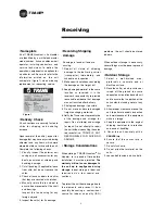
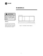
• Nameplate

All of TRANE Quantum

TM

 Air Handler

are identified by a multiple-character

model number.  lts use enables owner/

operator, installing contractors, and

service technicians to define the

operation, components and options for

a particular unit. Be sure to refer to the

information printed on the unit

nameplate (figure1) when ordering

replacement or requesting service.

• Delivery Check

All unit sections are securely fasten to

skids for shipping and handling

purpose.

Upon receipt of the unit(s), inspect for

damage that may have occurred during

shipment and any items, which were

ordered but did not arrive with the unit.

Complete the following checks:

1. Visually inspect the exterior unit

casing and all accessories for any

dents, punctures or shipping and

handling damage.

2. Cut all banding (if applicable) loose

from skid, but do not remove the

skids.

3. Check all access doors to confirm

that they are secured with latches.

4. Manually rotate the fan wheel to

ensure free movement of the shaft

and bearings

Inspect the fan housing for any

foreign objects.

5. Inspect the coil(s) for fin damage.

Figure 1

Summary of Contents for TRANE Quantum CLCPEuro

Page 1: ...TRANE R Installation Operation Maintenance IND SVN01A E4 Jan 2010 TRANE R TRANEQuantum TM Air Handler Model CLCPEuro CLCPXP...

Page 2: ...TRANE R...

Page 3: ...hould be recovered for reuse recovered and or recycled for reuse reprocessed reclaimed or properly destroyed whenever it is removed from equipment Never release to the atmosphere Safety Considerations...

Page 4: ...LCP euro Panel to Frame Connection CLCP euro Paneling CLCP euro Frame to Frame Connection CLCP XP Panel to Frame Connection CLCP XP Vertical Unit Final Filter Damper Joining Method Piping Start Up Sta...

Page 5: ...nit Description TRANE QuantumTM Air Handler are Central Station Air Handlers designed for a variety of controlled air application The basic unit consists of a fan heating and or cooling coils filters...

Page 6: ...TRANE R 2 CLCPXP Model Nomenclature...

Page 7: ...TRANE R CLCPEURO Model Nomenclature 3...

Page 8: ...raised off the ground to assure adequate air circulation beneath unit and to assure that no portion of the unit contacts standing water at any time 3 Allow proper clearance around the unit to perform...

Page 9: ...S RECEIVED FROM THE FACTORY Off Loading A specific lifting method for offloading the units is recommended as follows See Figure 2 1 75mm diameter lifting holes or certified lifting lugs are provided o...

Page 10: ...e unit base frame The lift point should be as near as possible to the centre of gravity see Figures 3 and 4 In the case of larger units the use of several forklift trucks may be required Roller Moveme...

Page 11: ...around the unit to ensure that correct operation and effective main tenance can be carried out Figure 6 gives recommended space allowances On the designated access side of the unit working areas must...

Page 12: ...rial such as cork slabbing TICO pads or rubber pad may be placed between the unit base and the foundation see Figure 8 Figure 8 Air Handling Unit Plinth Foundation IMPORTANT FAILURE TO PROVIDE A LEVEL...

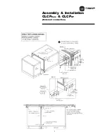
Page 13: ...TRANE R Assembly Installation CLCPEuro CLCPXP External connection 9...

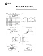
Page 14: ...TRANE R Assembly Installation CLCPEuro Break Point 25mm Frame to Frame 10...

Page 15: ...TRANE R 11 Assembly Installation CLCPEuro Break Point 25mm Panel to Frame...

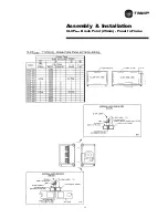
Page 16: ...TRANE R 12 Assembly Installation CLCPEuro Break Point 2 50mm Frame to Frame...

Page 17: ...TRANE R Assembly Installation CLCPEuro Break Point 2 50mm Panel to Frame 13...

Page 18: ...TRANE R Assembly Installation CLCPEuro Paneling 14...

Page 19: ...TRANE R Assembly Installation CLCP XP Break Point 15...

Page 20: ...TRANE R Assembly Installation CLCP XP Break Point 16...

Page 21: ...TRANE R 17 Assembly Installation CLCP...

Page 22: ...TRANE R Assembly Installation CLCP 18...

Page 23: ...pan When more than one module has a drain pan you must trap each module individually Connecting all drains to a common line with only one trap will result in condensate retention and possible water d...

Page 24: ...mum recommended torque is 200ft lbs 4 Teflon tape or teflon piping compound should not be used because of its high lubricity teflon makes it easier to tighten the pipe to the header joint past the poi...

Page 25: ...and continuos discharge operation Use float and thermostatic traps with atmospheric pressure gravity condensate return with automatic control or where the possibility of low pressure supply steam exis...

Page 26: ...SYSTEM CONTAMINATION DO NOT BREAK THE SEALS UNTIL THE COIL IS INSTALLED 1 Follow accepted refrigeration piping practices and safety precautions for typical refrigerant coil piping and components Speci...

Page 27: ...distributor tubing is not restricted or blocked To braze Thermostatic Expansion Valves TXV avoid direct flame figure 15 to the valve body and avoid excessive heat on diaphragm As an extra precaution...

Page 28: ...t 1 Inspect motor bearings for moisture and rust Replace bearings if necessary and repack with new grease 2 Check motor winding An acceptable winding resistance reading is from 6 meg ohms to infinity...

Page 29: ...d is changed more than 5 from the original designed rpm or if parts such as shafts fan wheels bear ings or other drive components are replaced Do not exceed max fan rpm 8 Pay particular attention to a...

Page 30: ...ht obstruct proper drainage Remove obstacles Check damper linkages set screws and blade adjustment for proper damper operation lnspect the control and power box wiring for secure connections and insul...

Page 31: ...Componetnts Controls Check the following Fan In General For Corrosion Flexible Connection Anti Vibration Mounts Drainage Fan Bearing Motors In General Motor Bearing Belt Drive In General Panel Or Bag...

Page 32: ...r manufacturer or Trane for lubrication instruction Most smaller frame motors comes without grease nipple where the bearings are permanently sealed The motors with double shielded bearings are lubrica...

Page 33: ...and drain line components 7 Allow the unit to dry thoroughly before putting the system back into service 8 Determine and correct the cause of the microbial contamination 9 Be careful that the contami...

Page 34: ...ut by the flanges between the grooves b Shiny pulley groove bottoms This is a sure sign that the belt has bottomed out The resulting slippage shortens belt life c Wobbling and or damaged pulleys Gener...

Page 35: ...mm of the drive With a belt tensioner at the center of the span apply a force K perpendicular to the span large enough to deflect the belt 15mm per 1 meter of span Refer to figure 17 The deflection f...

Page 36: ...TRANE R Maintenance 32 Figure 18 Belt Tension Measurement...

Page 37: ...and repair Replace bearings and seals Retighten hub Re tension and align Clean belts and pulleys check for grease leaks Remove obstruction Replace with full set Change at advised dirty condition Chec...

Page 38: ...ive for clearance Check belt tension and overhung load Replace sheave with larger one Blade bent Spindle or mechanism loose Actuator loose Air is by passing coil Coil tubes are blocked Incorrect airfl...

Page 39: ...TRANE R 35 Trouble Analysis Pulley and Belt...

Page 40: ...TRANE R 36 Appendix A HDT Unit Weight CLCPEURO 50mm Casing HDT Unit Weight kg _ Fan and Coil Sections without motor weight 25mm Casing 1 Coil weight is the operating weight...

Page 41: ...TRANE R Appendix A HDT Unit Weight CLCPEURO 37 Fan Coil Filter Sections without motor weight 50mm Casing 25mm Casing 1 Coil weight is the operating weight 2 Filter weight include filter media...

Page 42: ...E R Appendix A HDT Unit Weight CLCPEuro 38 Fan Coil Filter and Mixing Sections without motor weight 50mm Casing 25mm Casing Note 1 Coil weight is the operating weight 2 Filter weight includes filter m...

Page 43: ...TRANE R Appendix A VDT Unit Weight CLCPEuro 39 Note 1 Coil weight is the operating weight Fan and Coil Sections without motor weight 50mm Casing 25mm Casing...

Page 44: ...TRANE R Appendix A VDT Unit Weight CLCPEuro 40 50mm Casing Fan Coil Filter Sections without motor weight 25mm Casing Note 1 Coil weight is the operating weight 2 Filter weight includes filter media...

Page 45: ...TRANE R Appendix B HDT Unit Weight CLCPXP 41...

Page 46: ...TRANE R Appendix B HDT Unit Weight CLCPXP 42...

Page 47: ...TRANE R Appendix B HDT Unit Weight CLCPXP 43...

Page 48: ...TRANE R Appendix B VDT Unit Weight CLCPXP 44...

Page 49: ...8 0 5 2 5 4 4 2 4 6 1 0 19 72 50 3 2 8 1 6 7 8 9 6 5 0 6 3 4 5 6 7 4 2 4 4 0 2 0 21 79 56 7 1 0 1 8 3 9 8 5 8 8 4 7 8 6 6 4 8 5 1 4 5 5 2 0 24 88 65 6 1 2 1 4 1 1 1 2 1 0 1 6 7 8 4 7 7 4 6 6 0 1 6 0...

Page 50: ...FC 400 400 BC 400 014 FC 400 400 BC 400 016 FC 450 450 BC 450 020 FC 500 500 BC 500 025 FC 560 560 BC 560 030 FC 560 560 BC 560 035 FC 630 630 BC 630 040 FC 710 710 BC 710 045 FC 710 710 BC 710 050 FC...

Page 51: ...TRANE R Appendix D Filter and Quantity 47 Filter Dimension Nominal and Arrangement Flat Filter Bag Filter Cartridge Filter 10...

Page 52: ...TRANE R Appendix D Filter and Quantity 48 Filter Dimension and Arrangement High Capacity Filter CLCP Euro only...

Page 53: ...TRANE R Appendix D Filter and Quantity 49 Filter Dimension and Arrangement Final Filter HEPA...

Page 54: ...21 8 19 7 34 9 32 8 32 8 31 7 43 7 49 1 43 7 43 7 61 1 63 2 57 9 55 8 61 61 60 60 83 83 83 83 104 104 104 104 156 156 156 156 0 55 0 59 0 66 1 05 0 81 1 03 1 16 1 33 1 21 1 46 1 59 1 59 1 51 1 76 1 9...

Page 55: ...7 5 84 5 87 5 84 5 85 5 71 76 59 5 85 5 76 5 76 62 83 5 74 5 71 5 59 71 76 5 65 60 81 74 5 73 62 86 76 5 69 5 66 85 5 81 73 66 86 83 73 68 84 5 79 73 68 84 5 79 73 84 5 80 5 73 84 5 80 5 84 5 80 5 27...

Page 56: ...TRANE R 52 Typical unit wiring diagram CONNECTION DRAWING FOR BARE MOTOR CONNECTION DRAWING FOR TERMINATION 3 POLE CONNECTION DRAWING FOR TERMINATION 6 POLE...

Page 57: ...TRANE R Typical Wiring Diagram Starter Star Delta 380 420V 3Phase 4Wires ELCB Standard 53...

Page 58: ...TRANE R 54 Typical Wiring Diagram Starter Dol 380 420V 3Phase 4Wires ELCB Standard...

Page 59: ...TRANE R 55 Typical Wiring Diagram Starter Dol 380 420V 3Phase 4Wires Standard...

Page 60: ...TRANE R 56 Typical Wiring Diagram VFD Starter Dol Bypass Starter C W Door Switch 380 415 440 460V 3Phase 3Wires...

Page 61: ...TRANE R 57 Typical Wiring Diagram Starter Dol 380 420V 3Phase 4Wires ELCB Enhance with Thermistor Relay...

Page 62: ...TRANE R 58 Typical Wiring Diagram Starter Dol 380 420V 3Phase 4Wires Standard...

Page 63: ...TRANE R 59 Typical Wiring Diagram Starter Dol 380 420V 3Phase 4Wires Enhance with Thermistor Relay...

Page 64: ...TRANE R 60 Typical Wiring Diagram Starter Star Delta 380 420V 3Phase 4Wires Enhance with Thermistor Relay...

Page 65: ...TRANE R 61 Typical Wiring Diagram Starter Star Delta 380 420V 3Phase 4Wires Standard...

Page 66: ...right to alter any details of the products at any time without notice This publication is a general guide to install use and properly maintain our products The information given may be different from...

Page 67: ...brackets been removed Fan and Motor Alignment correct Belt tension condition good Belt guard in place and secure Do the fan rotates freely Electrical Installation Checks Electrical Cable entry at unit...

Page 68: ...TRANE R 64...

Page 69: ...Switch operation Mixing Box Economizer Dampers Outdoor Air Damper Operation check Return Air Damper Operation check Exhaust Air Damper Operation check Have the air dampers been inspected Supply Duct...

Page 70: ...TRANE R 66...

Page 71: ...TRANE R...

Page 72: ...and reserves the right to change design and specifications without notice Only qualified technicians should perform the instal lation and servicing of equipment referred to in this publication TRANE...

Reviews: