TRANE
R
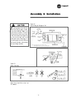
Sheave Alignment
Align the fan and motor sheaves by
using a straightedge. The straightedge
must be long enough to span the
distance between the outside edges
of the sheaves. For more details refer
to maintenance section.
Start - Up
25
The percent of voltage imbalance is
then calculated:
In this example, 2.2 percent imbalance
is not acceptable and the power
company should be notified to correct
it.
7. Check unit vibration if the fan speed
is changed more than 5% from the
original designed rpm, or if parts
such as shafts, fan wheels, bear-
ings, or other drive components are
replaced. Do not exceed max. fan
rpm.
8. Pay particular attention to any
vibration, noise or overheating of the
motor and fan bearings.
(Bearings may run warm during
break in.)
Excessive Vibration
EXCESSIVE VIBRATION MUST BE
CORRECTED TO PREVENT BEAR-
ING AND SHAFT DAMAGE. SEE THE
SECTION TITLED “TROUBLE-
SHOOTING” FOR DETAILS ON THE
COMMON CAUSES FOR VIBRATION.
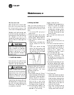
Determine Fan RPM
Fan rpm can be determined by using a
strobe-type tachometer, or revolution
counter.
100 x {[226-221] + [230-226] + [227-226]}
2 x 226
= 2.2% (Unacceptable)
Summary of Contents for TRANE Quantum CLCPEuro
Page 2: ...TRANE R...
Page 6: ...TRANE R 2 CLCPXP Model Nomenclature...
Page 7: ...TRANE R CLCPEURO Model Nomenclature 3...
Page 13: ...TRANE R Assembly Installation CLCPEuro CLCPXP External connection 9...
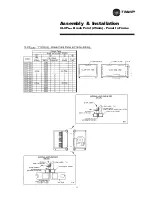
Page 14: ...TRANE R Assembly Installation CLCPEuro Break Point 25mm Frame to Frame 10...
Page 15: ...TRANE R 11 Assembly Installation CLCPEuro Break Point 25mm Panel to Frame...
Page 16: ...TRANE R 12 Assembly Installation CLCPEuro Break Point 2 50mm Frame to Frame...
Page 17: ...TRANE R Assembly Installation CLCPEuro Break Point 2 50mm Panel to Frame 13...
Page 18: ...TRANE R Assembly Installation CLCPEuro Paneling 14...
Page 19: ...TRANE R Assembly Installation CLCP XP Break Point 15...
Page 20: ...TRANE R Assembly Installation CLCP XP Break Point 16...
Page 21: ...TRANE R 17 Assembly Installation CLCP...
Page 22: ...TRANE R Assembly Installation CLCP 18...
Page 36: ...TRANE R Maintenance 32 Figure 18 Belt Tension Measurement...
Page 39: ...TRANE R 35 Trouble Analysis Pulley and Belt...
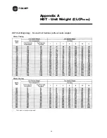
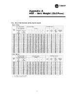
Page 45: ...TRANE R Appendix B HDT Unit Weight CLCPXP 41...
Page 46: ...TRANE R Appendix B HDT Unit Weight CLCPXP 42...
Page 47: ...TRANE R Appendix B HDT Unit Weight CLCPXP 43...
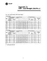
Page 48: ...TRANE R Appendix B VDT Unit Weight CLCPXP 44...
Page 53: ...TRANE R Appendix D Filter and Quantity 49 Filter Dimension and Arrangement Final Filter HEPA...
Page 57: ...TRANE R Typical Wiring Diagram Starter Star Delta 380 420V 3Phase 4Wires ELCB Standard 53...
Page 58: ...TRANE R 54 Typical Wiring Diagram Starter Dol 380 420V 3Phase 4Wires ELCB Standard...
Page 59: ...TRANE R 55 Typical Wiring Diagram Starter Dol 380 420V 3Phase 4Wires Standard...
Page 62: ...TRANE R 58 Typical Wiring Diagram Starter Dol 380 420V 3Phase 4Wires Standard...
Page 65: ...TRANE R 61 Typical Wiring Diagram Starter Star Delta 380 420V 3Phase 4Wires Standard...
Page 68: ...TRANE R 64...
Page 70: ...TRANE R 66...
Page 71: ...TRANE R...

