


TRANE
R
Start - Up
Perform the following steps prior to
starting the unit.
1. Inspect electrical connections. They
should be clean and secure.
Compare actual wiring with specific
diagrams provided on the unit.
2. Check piping and valves for leaks.
Open or close the valves to check
for proper operation. Drain lines
should be open.
3. If equipped with a refrigerant coil,
charge and leak-test the unit and
get it ready for operation according
to instructions provided with the
condenser equipment.
4. Check that all air filters are in place
and positioned properly. Under
Periodic Maintenance, see section
titled “Air Filters.”
5. Close and secure all unit access
doors. Check that the latch set
screws are tight.
6. Remove all foreign material from the
CAUTION
!
drain pan and check drain opening
and condensate line for obstruc-
tions.
7. Prime the DRAIN TRAP.
Start-up Procedures
After completing all start-up checks
and procedures, the unit may be
started. The following checks and
adjustments should be made during
initial start-up:
24
The use of untreated or
improperly treated water
in unit coils may cause
scaling, erosion, corro-
sion, algae, smile or other
equipment damage.
Consult a qualified water
treatment specialist to
determine if water
treatment is required. The
Trane Company assumes
no respon-sibility for
equipment damage
caused by untreated or
improperly treated water.
If the unit was stored for an extended
period of time, the following items
should be checked before starting the
unit.
1. Inspect motor bearings for moisture
and rust. Replace bearings if
necessary and repack with new
grease.
2. Check motor winding. An
acceptable winding resistance
reading is from 6 meg-ohms to
infinity. If reading is less than
5 meg-ohms, winding should be
dried out in an oven or by a
blower.
3. Inspect the entire motor for rust and
corrosion.
4. Lubricate the motor as instructed in
the section titled “Periodic
Maintenance,” or as indicated by the
maintenance tag on the motor.
5. Bump-start unit and observe the fan
wheel for proper rotation, as
indicated by rotation arrow located
on fan housing.
6. Measure the motor voltage and
ampeage on all phases to ensure
proper operation. The readings
should fall within the range given
on the motor nameplate.
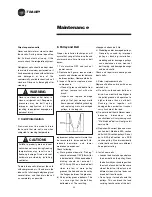
Maximum allowable voltage imbalance
is two percent. Voltage imbalance is
defined as 100 times the sum of the
deviation of the three voltage from the
average, divided by twice the average
voltage. For example, if the three
measured voltages are 221, 230 and
227, the average would be 226 volts.
WARNING
!
Disconnect electrical
power prior to access into
a fan or ductwork. Even
when locked out
electrically, fans may
cause injury or damage if
the impeller is subject to
“wind-milling.” The
impeller should be
secured to physically
restrict rotational move-
ment. Failure to secure
impeller can cause severe
personal injury r death.
Disconnect electrical
power source when
connecting or discon-
necting electrical wires for
test procedures. Do not
open service access
doors while the unit is
operating. Failure to
exercise caution or while
inspecting. unit operation
may result in injury or
death from electrical
shock, air movement or
rotating parts.
Summary of Contents for TRANE Quantum CLCPEuro
Page 2: ...TRANE R...
Page 6: ...TRANE R 2 CLCPXP Model Nomenclature...
Page 7: ...TRANE R CLCPEURO Model Nomenclature 3...
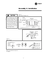
Page 13: ...TRANE R Assembly Installation CLCPEuro CLCPXP External connection 9...
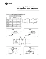
Page 14: ...TRANE R Assembly Installation CLCPEuro Break Point 25mm Frame to Frame 10...
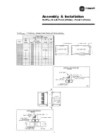
Page 15: ...TRANE R 11 Assembly Installation CLCPEuro Break Point 25mm Panel to Frame...
Page 16: ...TRANE R 12 Assembly Installation CLCPEuro Break Point 2 50mm Frame to Frame...
Page 17: ...TRANE R Assembly Installation CLCPEuro Break Point 2 50mm Panel to Frame 13...
Page 18: ...TRANE R Assembly Installation CLCPEuro Paneling 14...
Page 19: ...TRANE R Assembly Installation CLCP XP Break Point 15...
Page 20: ...TRANE R Assembly Installation CLCP XP Break Point 16...
Page 21: ...TRANE R 17 Assembly Installation CLCP...
Page 22: ...TRANE R Assembly Installation CLCP 18...
Page 36: ...TRANE R Maintenance 32 Figure 18 Belt Tension Measurement...
Page 39: ...TRANE R 35 Trouble Analysis Pulley and Belt...
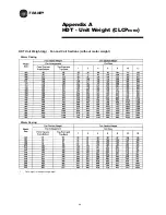
Page 45: ...TRANE R Appendix B HDT Unit Weight CLCPXP 41...
Page 46: ...TRANE R Appendix B HDT Unit Weight CLCPXP 42...
Page 47: ...TRANE R Appendix B HDT Unit Weight CLCPXP 43...
Page 48: ...TRANE R Appendix B VDT Unit Weight CLCPXP 44...
Page 53: ...TRANE R Appendix D Filter and Quantity 49 Filter Dimension and Arrangement Final Filter HEPA...
Page 57: ...TRANE R Typical Wiring Diagram Starter Star Delta 380 420V 3Phase 4Wires ELCB Standard 53...
Page 58: ...TRANE R 54 Typical Wiring Diagram Starter Dol 380 420V 3Phase 4Wires ELCB Standard...
Page 59: ...TRANE R 55 Typical Wiring Diagram Starter Dol 380 420V 3Phase 4Wires Standard...
Page 62: ...TRANE R 58 Typical Wiring Diagram Starter Dol 380 420V 3Phase 4Wires Standard...
Page 65: ...TRANE R 61 Typical Wiring Diagram Starter Star Delta 380 420V 3Phase 4Wires Standard...
Page 68: ...TRANE R 64...
Page 70: ...TRANE R 66...
Page 71: ...TRANE R...