Installation
42
WSHP-SVX13C-EN
connection of a Hays Measurflo® balancing hose kit to the
water-in and water-out of a vertical unit.
Note:
Figure 27, p. 41
example incorporates the Hays
Measurflo® balancing hose kit and a 2-position
isolation valve into the system design. An isolation
valve is often used in variable-speed pumping
applications. The isolation valve is designed to
stop water flow to the unit during non-operation
times.This allows the loop water pumps to run only
when a requirement for pumping is needed for
greater energy efficiency of the overall system
design.
System balancing hose kit
For automatic system balancing of a water source heat
pump, the Mesurflo® self-balancing hose kit provides a
constant flow rate over the pressure differential rage of 2
to 80 psid. As system pressure changes (through further
addition of heat pumps, for example) each individual flow
control valve will automatically adjust to the new system
conditions. In variable water volume applications, a self-
balancing hose kit can provide continuous balancing
because of its ability to automatically adjust to the varying
system conditions.
Note:
At low differential pressure the flow area required
to achieve higher flow can exceed the flow area
available for the respective series.Therefore, the
minimum pressure differential requirement is
increased for the higher flow ranges of each series
Mesurflo valve.
Additional accessories, such as a strainer are
recommended for use to eliminate contaminants from
entering the co-axial water-to-refrigerant heat exchanger.
Cleaning and Flushing the Water Loop
After the piping system is complete, the flexible hose
connectors should be disconnected from the unit and
linked together using field supplied couplings (avoiding
trash settle-out in the condenser). An extra pipe may be
necessary to connect the hose kits.
1. Water circulation system should be filled with clean
water using the water make up connections.
Note:
Air vents should be open during filling.
2. With the air vents closed, start the circulating pump
and then crack the air vents to bleed off the trapped air,
assuring circulation through all components of the
system.
Note:
Make up water must be available to the system to
replace the volume formerly occupied by the air
that is bled off.
3. With the air vented and the water circulating, the entire
system should be checked for leaks with repairs made
as required.
4. Operate the supplementary heat system (boiler) if
applicable making checks per manufacturer’s
instructions. During this operation, visual checks
should be made for leaks that may have occurred due
to increased heat. Repair as required.
5. Open the system at the lowest point for the initial blow
down (making sure the make up water is equal to the
water being dumped). Continue blow down until the
water leaving the drain runs clear, but not less than 2
hours.
6. Shut down pumps and supplementary heat system (if
applicable). Reconnect the hoses placing the water-to-
refrigerant heat exchanger in the water circulating
system.
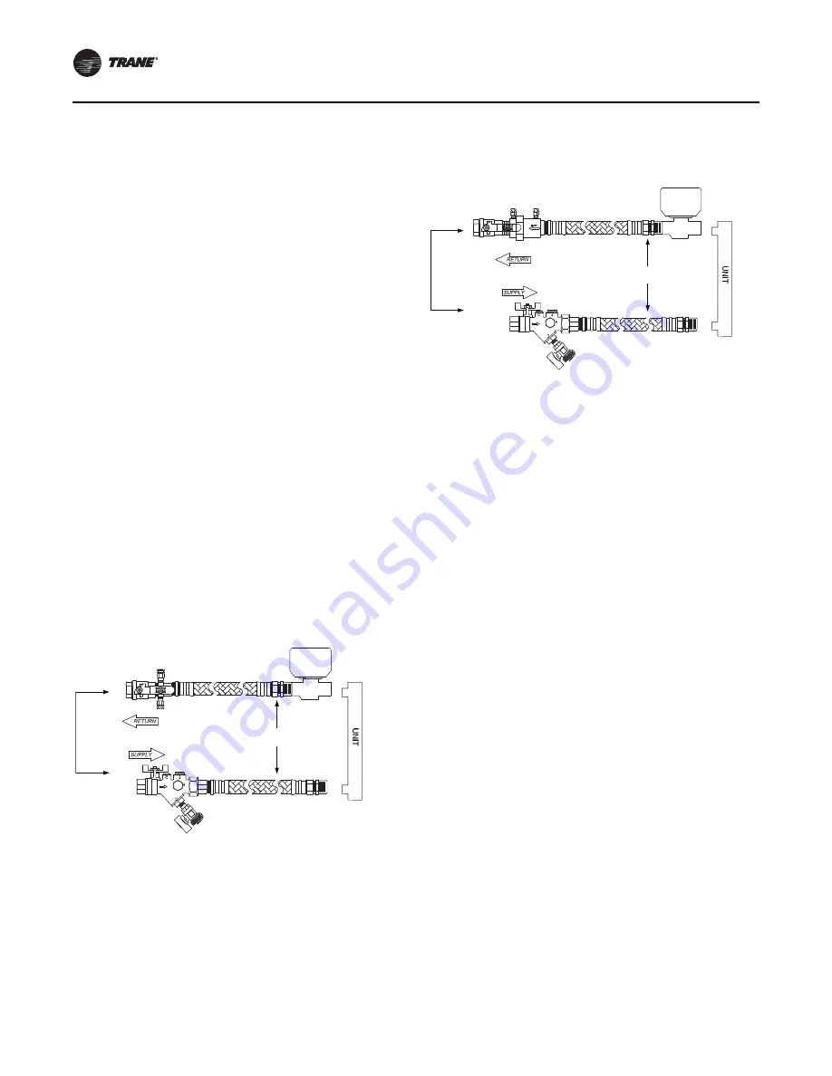
Figure 28. Ball valve kit (manual)
Flex Hose
Mesurmeter w/PT’s
Optional Yball Strainer
w/Blowdown Valve &
Hose Connector
PT
FLOW
Ball Valve
Optional Isolation Valve
2-Position Valve
AUTOMATIC
TEMPERATURE
CONTROL
VALVE
Figure 29. MeasurfloVac kit (automatic)
Flex Hose
Optional Yball Strainer
w/Blowdown Valve &
Hose Connector
PT
FLOW
Ball Valve
Optional Isolation Valve
2-Position Valve
2510 Mesurflo w/PT’s
AUTOMATIC
TEMPERATURE
CONTROL
VALVE


