56
WSHP-SVX01E-EN
Installation
Controls Using 24 VAC
Before installing any wire, refer to the
electrical access locations in
Dimension section of this manual.
Ensure that the AC control wiring
between the controls and the unit’s
termination point does not exceed
three (3) ohms/conductor for the
length of the run.
Note:
Resistance in excess of 3-
ohms per conductor may
cause component failure due
to insufficient AC voltage
supply.
Check all loads and conductors for
grounds, shorts, and mis-wiring.
Use copper conductors unless
otherwise specified.
Do not run the AC low voltage wiring
in the same conduit with the high
voltage power wiring.
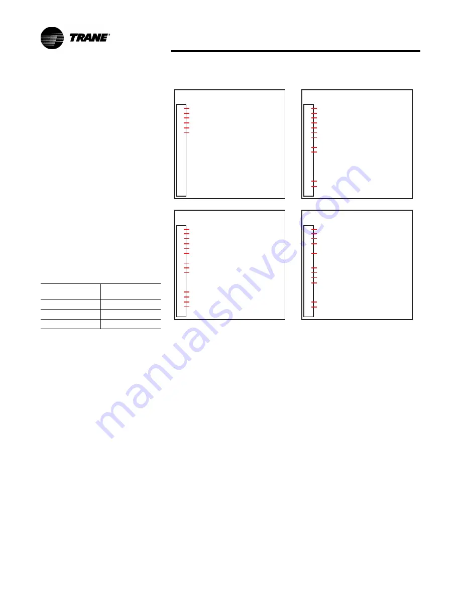
Low voltage connection diagrams for
basic and deluxe 24 volt control
packages mounted on 1/2 through 5
ton equipment sizes are shown in
Figure 62
.
Table 33. 24V AC conductors
Distance from unit
to Control
Recommended
Wire Size
000-460 feet
18 gauge
461-732 feet
16 gauge
733-1000 feet
14 gauge
Figure 62.
Low voltage connection (1/2 through 5 ton equipment)
B
a
s
ic
Controls W
a
ll Mounted Thermost
a
t
1
2
3
4
5
6
7
8
9
10
11
12
13
1
4
15
16
17
18
1TB1
2
4
VAC
FAN
REVERSIN
G
VALVE (COOL)
COMPRESSOR & VAR SPD PUMP SOLENOID
2
4
VAC
G
ENERAL ALARM OUTPUT
2
4
VAC COMMON & VAR SPD PUMP SOLENOID
Deluxe Controls W
a
ll Mounted Thermost
a
t
1
2
3
4
5
6
7
8
9
10
11
12
13
1
4
15
16
17
18
1TB1
2
4
VAC
FAN
REVERSIN
G
VALVE (COOL)
COMPRESSOR & VAR SPD PUMP SOLENOID
2
4
VAC COMMON & VAR SPD PUMP SOLENOID
ELECTRIC HEAT (COOL ONLY W/ ELEC HT UNIT)
2
4
VAC COMPRESSOR DISABLE INPUT
2
4
VAC COMPRESSOR DISABLE INPUT
ALARM CONTACT OUTPUT
ALARM CONTACT OUTPUT
Deluxe Controls NSB Thermost
a
t
1
2
3
4
5
6
7
8
9
10
11
12
13
1
4
15
16
17
18
1TB1
"L" THERMOSTSAT TERMINAL
FAN
REVERSIN
G
VALVE (COOL)
COMPRESSOR & VAR SPD PUMP SOLENOID
2
4
VAC COMMON & VAR SPD PUMP SOLENOID
"R" THERMOSTAT TERMINAL
2
4
VAC COMPRESSOR DISABLE INPUT
2
4
VAC COMPRESSOR DISABLE INPUT
2
4
VAC NI
G
HT SETBACK INPUT
2
4
VAC NI
G
HT SETBACK INPUT
ALARM CONTACT OUTPUT
ALARM CONTACT OUTPUT
Deluxe Controls W
i
th Rehe
a
t
1
2
3
4
5
6
7
8
9
10
11
12
13
1
4
15
16
17
18
1TB1
2
4
VAC
FAN
REVERSIN
G
VALVE (COOL)
COMPRESSOR
2
4
VAC COMMON & VAR SPD PUMP SOLENOID
2
4
VAC COMPRESSOR DISABLE INPUT
2
4
VAC COMPRESSOR DISABLE INPUT
HUMIDISTAT
VAR SPD PUMP SOLENOID
ALARM CONTACT OUTPUT
ALARM CONTACT OUTPUT
Summary of Contents for Axiom GEHB 006
Page 88: ...88 WSHP SVX01E EN Figure 1 Basic 208 V 60 Hz 1Ph Wiring...
Page 89: ...WSHP SVX01E EN 89 Wiring Figure 2 Deluxe 380 420 V 50 Hz 3 Ph...
Page 90: ...90 WSHP SVX01E EN Wiring Figure 3 ZN510 208 V 60 Hz 1 Ph...
Page 91: ...WSHP SVX01E EN 91 Wiring Figure 4 ZN524 460 V 60 Hz 3 Ph...
Page 95: ......


