WSHP-SVX01E-EN
57
Installation
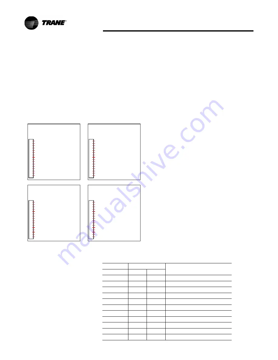
Controls Using 24 VAC
There are two factory thermostat
options for the dual circuited (6
through 25 ton) equipment. Low
voltage connection diagrams for
deluxe 24 volt control packages for
these thermostats mounted on 6
through 25 ton equipment sizes are
shown in
Figure 63
.
For controls using DC analog input/
outputs, see appropriate installation,
operation and diagnostic manuals for
connection. WSHP-IOP-2 (ZN510) and
WSHP-PRB002-EN (ZN524).
Deluxe Board Diagnostics
Three light emitting diodes (LEDs)
are provided for indicating the
operating mode of the Deluxe
Controller. The LEDs are intended to
aid in troubleshooting and for unit
maintenance. The LEDs are labeled
on the circuit board with numbers as
referenced in
Table 34
.
Figure 63.
Low voltage connection (6 to 25 ton)
Deluxe Controls w
i
th
-
a
ll He
a
t Pum
p
Un
i
ts w/ Rehe
a
t
-
a
ll Cool
i
n
g
Only Un
i
ts
us
i
n
g
X13511090010 (T8511)
1
2
3
4
5
6
7
8
9
10
11
12
13
1
4
15
16
1TB2
2
4
VAC (R)
FAN (
G
)
COMPRESSOR 1 (Y1)
COMPRESSOR 2 (Y2)
REVERSIN
G
VALVE (0) & HUMIDISTAT
2
4
VAC COMMON (C) & WATER ISOLATION VA
COMPRESSOR DISABLE
COMPRESSOR DISABLE
ALARM
ALARM
ELECTRIC HEAT
ELECTRIC HEAT
HUMIDISTAT
WATER ISOLATION VALVE
3RD STA
G
E HEAT (W3)
NOT USED
Deluxe Controls w
i
th
-
a
ll He
a
t Pum
p
Un
i
ts w/ Rehe
a
t
-
a
ll Cool
i
n
g
Only Un
i
ts
us
i
n
g
X13511091010/X13511092010 (T7300)
1
2
3
4
5
6
7
8
9
10
11
12
13
1
4
15
16
1TB2
2
4
VAC (R)
FAN (
G
)
COMPRESSOR 1 (Y1)
COMPRESSOR 2 (Y2)
REVERSIN
G
VALVE (0) & HUMIDISTAT
2
4
VAC COMMON (X) & WATER ISOLATION VA
COMPRESSOR DISABLE
COMPRESSOR DISABLE
ALARM
ALARM
ELECTRIC HEAT
ELECTRIC HEAT
HUMIDISTAT
WATER ISOLATION VALVE
3RD STA
G
E HEAT (W1)
NOT USED
Deluxe Controls w
i
th
-
a
ll He
a
t Pum
p
Un
i
ts w
i
thout Rehe
a
t
us
i
n
g
X13511090010 (T8511)
1
2
3
4
5
6
7
8
9
10
11
12
13
1
4
15
16
1TB2
2
4
VAC (R)
FAN (
G
)
COMPRESSOR 1 (Y1) & WATER ISOLATION VA
COMPRESSOR 2 (Y2)
REVERSIN
G
VALVE (0) & HUMIDISTAT
2
4
VAC COMMON (C) & WATER ISOLATION VA
COMPRESSOR DISABLE
COMPRESSOR DISABLE
ALARM
ALARM
ELECTRIC HEAT
ELECTRIC HEAT
HUMIDISTAT
NOT USED
3RD STA
G
E HEAT (W3)
NOT USED
Deluxe Controls w
i
th
-
a
ll He
a
t Pum
p
Un
i
ts w
i
thout Rehe
a
t
us
i
n
g
X13511091010/X13511092010 (T7300)
1
2
3
4
5
6
7
8
9
10
11
12
13
1
4
15
16
1TB2
2
4
VAC (R)
FAN (
G
)
COMPRESSOR 1 (Y1) & WATER ISOLATION VA
COMPRESSOR 2 (Y2)
REVERSIN
G
VALVE (0) & HUMIDISTAT
2
4
VAC COMMON (X) & WATER ISOLATION VA
COMPRESSOR DISABLE
COMPRESSOR DISABLE
ALARM
ALARM
ELECTRIC HEAT
ELECTRIC HEAT
HUMIDISTAT
NOT USED
3RD STA
G
E HEAT (W1)
NOT USED
Table 34. Deluxe controller diagnostic
LEDs
Color: Green Color: Red
Controller
Mode
LED1
LED2
LED3
OFF
OFF
OFF
Control OFF
ON
OFF
OFF
Normal/Compressor OFF
ON
OFF
FLASH
Anti-short cycle
ON
OFF
ON
Normal/Compressor ON
FLASH
ON
OFF
Brownout Condition
ON
FLASH
ON
Soft Lockout (low pressure)
ON
FLASH
FLASH
Soft Lockout (high pressure)
ON
ON
ON
Manual Lockout (low pressure)
ON
ON
FLASH
Manual Lockout (high pressure)
ON
FLASH
OFF
Manual Lockout (condensate overflow)
ON
ON
OFF
Compressor Disable
Summary of Contents for Axiom GEHB 006
Page 88: ...88 WSHP SVX01E EN Figure 1 Basic 208 V 60 Hz 1Ph Wiring...
Page 89: ...WSHP SVX01E EN 89 Wiring Figure 2 Deluxe 380 420 V 50 Hz 3 Ph...
Page 90: ...90 WSHP SVX01E EN Wiring Figure 3 ZN510 208 V 60 Hz 1 Ph...
Page 91: ...WSHP SVX01E EN 91 Wiring Figure 4 ZN524 460 V 60 Hz 3 Ph...
Page 95: ......


