17
90
90
C) BLOCSTOP
®
BSO 2050
(Installation dimensions on page 18)
a)
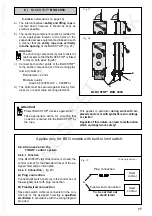
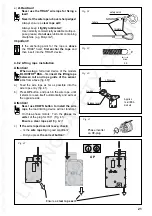
The interval between safety and lifting rope is
not laid down; however it should be kept as
small as possible.
b)
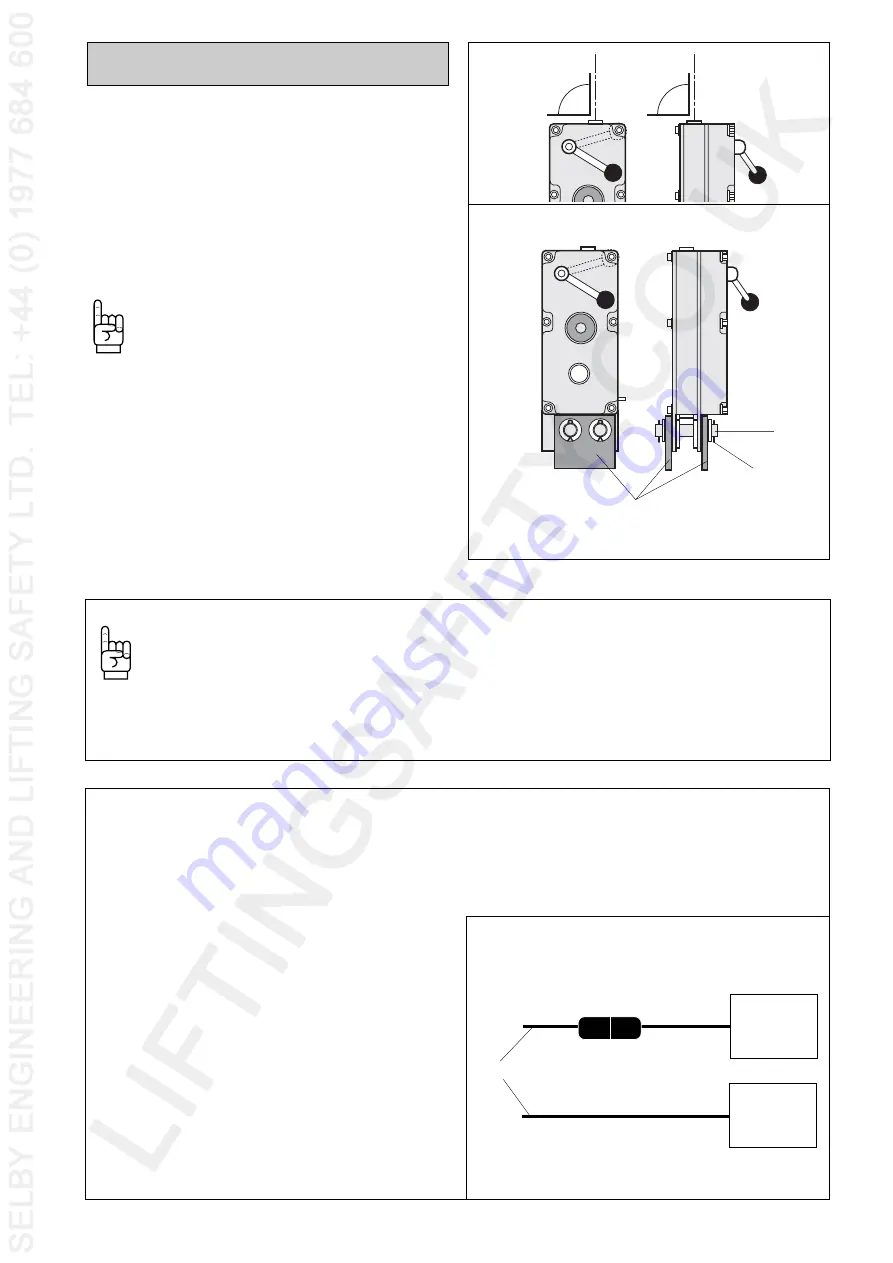
The anchoring component must be provided for
at an appropriate interval to the hoist on the
suspended access equipment and indeed in such
a manner that the safety rope runs vertically
into the opening of the BLOCSTOP
®
(fig. 27).
Attention!
The anchoring component (a) must consist of
two brackets so that the BLOCSTOP
®
is linked
to this on both sides (fig.28).
c)
Connect both anchor points of the BLOCSTOP
®
to the anchor component (a) of the working plat-
form with bolts (b).
Bolt diameter: 22 mm
Minimum quality:
Grade 8.8 (800 N/mm
2
800 MPa)
d)
The bolts must be secured against loss by fore-
locks (c) or equal value securing elements.
Fig. 27
Fig. 28
a
b
c
Applies only for BSO models with built-in limit switch:
4.4.4 Connection to the
TIRAK
®
control system
4.4.4.1 Function
If the BLOCSTOP
®
fall arrest device is closed, the
control current for the downward travel of the as-
signed hoist will be interrupted.
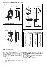
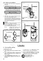
4.4.4.2 Connection ( fig. 29)
A) Plug connection
Connect limit switch cable (a) to the control box of
the assigned hoist with plug connection.
B) Fixed wired connection
Have limit switch cable (a) connected in the con-
trol box of the assigned hoist by a qualified
electrician in accordance with the wiring diagram
provided.
Fig. 29
a
Hoist
control
Plug connection
Hoist
control
Fixed wired connection
To be carried out
by electrician!
(Principle sketch)
Attention!
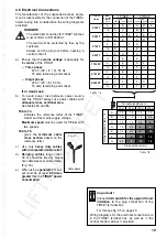
Protect BLOCSTOP
®
devices against dirt!
Take appropriate action for ensuring that
no debris is carried into the BLOCSTOP
©
by
the rope.
This applies in particular during work with air-
placed concrete or with synthetic resin coatings
or similar!
Deposits of this nature can lead to malfunction
which endanger work safety!
BLOCSTOP
®
BSO 2050


