


Reviews:
No comments
Related manuals for VP-6ED
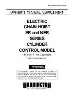
ER Series
Brand: Harrington Hoists Pages: 12
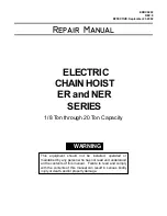
ER Series
Brand: Harrington Pages: 71
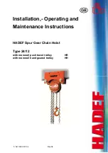
24/12
Brand: HADEF Pages: 18
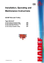
20/94 AF Series
Brand: HADEF Pages: 16
CF4
Brand: Harrington Pages: 30

TX600
Brand: Mackworth Pages: 38
CPE Series
Brand: Yale Pages: 32
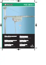
PSZ 250 A1
Brand: Parkside Pages: 30
PSZ 250 A2
Brand: Parkside Pages: 40
PSZ 250 A1
Brand: Parkside Pages: 40
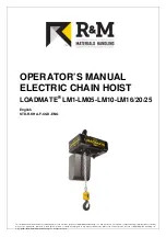
LOADMATE LM 01
Brand: R&M Pages: 42
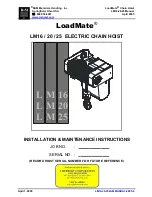
LOADMATE LM 16
Brand: R&M Pages: 58
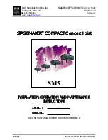
STAGEMAKER SM5
Brand: R&M Pages: 52

PT
Brand: Yale Pages: 12
Gold Series
Brand: Vanguard Pages: 10
UNOplus
Brand: Yale Pages: 18
VLP Series
Brand: Jet Pages: 9
622 Series
Brand: U-Line Pages: 12


