
Parameterization and configuration
TR-Electronic GmbH 2009, All Rights Reserved
Printed in the Federal Republic of Germany
Page 84 of 92
TR - ELA - BA - DGB - 0015 - 13
04/23/2020
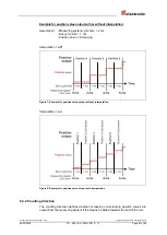
6.5 Preset adjustment function
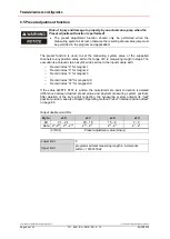
Risk of injury and damage to property by an actual value jump when the
Preset adjustment function is performed!
The preset adjustment function should only be performed when the
measuring system is at rest, otherwise the resulting actual value jump must
be permitted in the program and application!
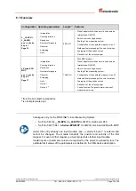
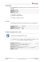
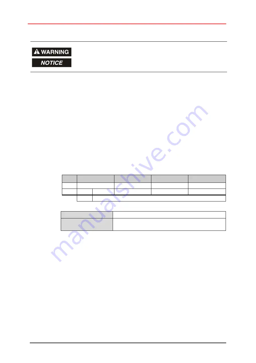
The preset function is used to set the measuring system value of the supported
channels to any position value within the range of 0 to measuring length in steps. The
execution is achieved via an acyclic write service to the input module with:
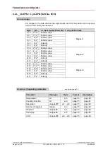
o
Record index “2” for magnet 1
o
Record index “3” for magnet 2
o
Record index “4” for magnet 3
o
o
Record index “30” for magnet 29
o
Record index “31” for magnet 30
If the value 0x3FFF FFFF is written, the calculated zero point correction is deleted
(difference between desired preset value and physical measuring system position).
After deletion of the zero point correction, the measuring system outputs its "real"
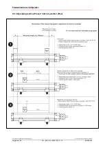
physical position, see also chapter “Operating method Preset / internal position offset”
on page 86.
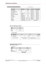
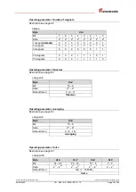
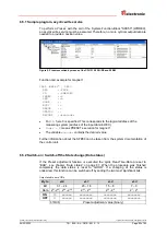
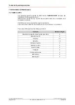
Output double word ODx
Byte
x+0
x+1
x+2
x+3
Bit
31
– 24
23
– 16
15
– 8
7
– 0
Data 2
31
-2
30
2
29
- 2
24
2
23
- 2
16
2
15
- 2
8
2
7
- 2
0
STATUS
Preset adjustment value (binary)
Lower limit
0
Upper limit
programmed total measuring length in increments,
within
1073741822


