TQC CureView AB8000 Operating Instructions Manual Download Page 15

15   |

11.1 General

Even though the CureView is designed to the highest specifications possible 
the CureView has limitations. We simply are not able to go beyond the laws 
of physics. In order to explain some of the limitations of the TQC CureView 
the following chapter will include some of the intricacies of thermal 
dynamics involved with using the CureView.

11.2 Basics of Gradient Ovens:

The TQC CureView is a new generation of Gradient-ovens that allows for 
significantly more advanced tests and doesn’t require preheating. The
implementation of the latest heating techniques in the TQC CureView 
provide a different heat transfer compared to that of older systems with 
conventional heating. The direct IR-irradiation by the TQC CureView allows 
for a significantly more efficient heating than traditional gradient oven 
systems. Due to this new heating system multiple components and 
procedures had to be changed in the machine. Below is a simplified image 
highlighting the difference in build of conventional systems and the new 
TQC CureView.

Due to the difference in construction the heat transfer is significantly 
different. Where the older systems work based on conduction of heat the 
TQC CureView is based on transmittance of energy by IR-radiation. Older 
Gradient ovens often suffer from loss in efficiency by improper contact
between the heating element, glass-bed and/or test panel. Because older 
models have the thermocouple installed directly at the heater, they have 
been compensated for the offset that occurs due to the different contacts 
required to transfer the heat. Any small misalignment or other problem will 
result in a loss of efficiency. This will cause significant differences in the 
temperature of the test-panel. The TQC CureView is created such that it 
regulates the heaters based on the temperature probe that is positioned on 
top of the panel, thus at the actual spot where the temperature is relevant. 
When comparing old and new systems side by side there might be a 
temperature offset that has to be accounted for. This off-set is due to 
deviation from older machines. Where test were set to be performed at 
180˚C / 356˚F they could actually have been performed at 150˚C / 302˚F. 
This off-set varies depending on the condition of the old machines. 
To determine this off-set it is recommended to measure the actual 
temperature obtained on the surface of the test panel. 

Due to the new and improved heating systems no preheating is required. 
This eliminates an irregular heating of the panel and allows for a repeatable 
ramping of the temperature on the panel. The ramping is controlled and will 
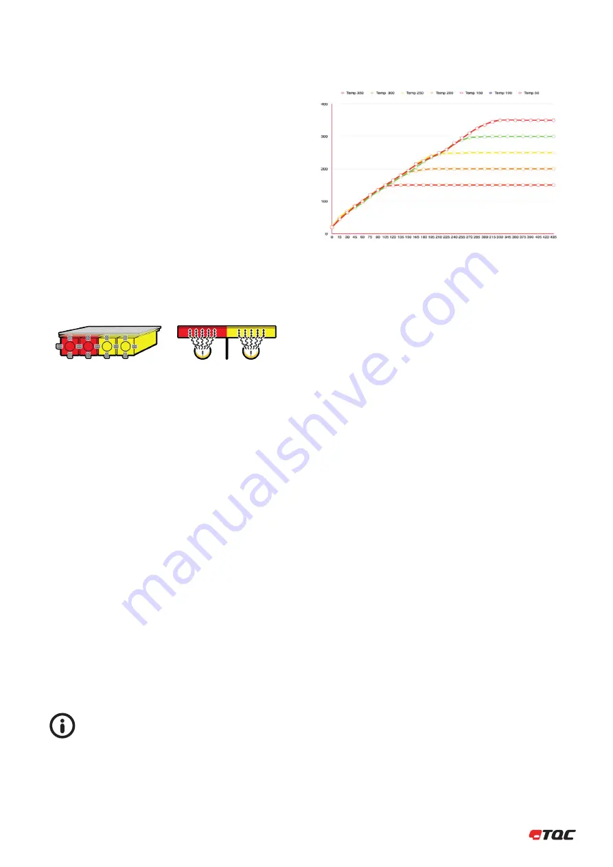
follow the same slope for all temperatures. The ramping for the heating can 
be programmed in the Gradient oven.  Below graph shows a default slope 
being equal for all set point temperatures.


All following examples of ramping and heating graphs are  


generalized and not correlated to a specific substrate or  


ramp speed unless otherwise stated.

In the following graph the vertical axis shows the temperature in ˚C and the 
horizontal axis displays the time (s). All set temperatures follow the same 
ramp. Adjusting the ramp value can control the ramp slope.

11.3 Substrate material

The main influence for differences between tests is the substrate that tests 
are performed on. Different substrates react differently to heat. Some 
substrate function as an isolator and others as an excellent conductor of 
heat. This ability or it’s lack to conduct heat determine the maximal 
temperature difference between 2 heaters. On a well conducting material 
the difference between 2 elements is lower than on a less conducting 
substrate. The property of metals to conduct heat is a temperature 
dependent function. If a gradient from 25˚C to 125˚C / 77˚F to 257˚F 
is obtainable this doesn’t mean that 125°C to 225°C / 257˚F to 437˚F is 
possible as well or vice versa. In order to test for the suitability of a program 
and/or substrate it is advised to run a test-run on uncoated substrate prior 
to performing the real test.

Full thermal properties of a substrate can be calculated. Full calculations 
and factors can be found in the “ Handbook of Chemistry and physics.” 
Calculating the thermal response of panels is however tricky due to the 
large number of variables. 

11.4 Surrounding / environmental conditions.

The TQC CureView has been designed such that it will keep draft away 
from the panel but still allow the panel to be visible. Though the Cureview 
is designed to eliminate as many influences as possible. Small fluctuations 
in the heating behavior can be caused by changes in temperature and 
humidity of the surrounding air. These parameters not only influence 
the heating capabilities of the CureView but in more significant manner 
the evaporation of samples as tested according the ISO 2812-5 or curing 
of powder coatings. Stable laboratory conditions are required to create 
reproducible results. Please consult internal guidelines or international 
standards for the required climatic conditions required for the performed 
test.

11.5 Ramping

The TQC CureView can be set for custom ramping speeds. A Ramping 
indicates the speed in degree per second the CureView will heat a panel. 
The selected ramping will influence the amount of heat generated by the 
lamps. The generated heat needs to flow from the bottom of the panel to 
the top prior to being detected by the probes. This process depends on 
the thermal properties of the test panel. Thickness, material type, surface 
finishing and set end temperature all influence the thermal response. If the 
ramping is set to high there might be an overshoot of the set temperature. 

11 THERMAL DYNAMICS

Conventional heating

IR-heating

Summary of Contents for CureView AB8000

Page 1: ...ew Gradient Oven AB8000 REV02 Gradient oven with GOC and Ideal Finish control Operating Instructions V1 2 0918 IMPORTANT Before taking this instrument in use we strongly advise you to read this manual...

Page 2: ......

Page 3: ...ion 6 Instrument Controls and Functions 7 Instrument Preparations 7 1 Test Panels 7 2 Calibration Interval 7 3 Lamp Maintenance 7 4 Software 8 Operation 8 1 Preparatory Work 8 2 Sample Preparation 8 3...

Page 4: ...anyone appointed to work with the instrument should pay attention to the general regulations relating to working safety and accident prevention The safety chapter and the warnings in this manual shou...

Page 5: ...heated area after the instrument has started Possible immediate danger to the life or health of personnel If this guideline is not noted it can lead to severe danger to health up to fatal injury A da...

Page 6: ...damage should be documented as accurately as possible possibly photographed and reported to the relevant insurers or in the case of sales delivered to customers works to the supplier 3 4 Storage and P...

Page 7: ...ght 296 mm 11 65 inch Net weight approx 31 kg 68 34 inch 4 5 Basic Unit Power Supply 220 240 V 50 60 Hz single phase split phase Power consumption max 3000 Watt Display None status indication by 2 LED...

Page 8: ...12 5 Panel Adapter suitable for Holding Panels size 500 mm x 100 mm Spare parts AB8016 Halogen Gold Reflector Infrared Heating Lamp set of 10 pcs AB8020 Lamp Replacement Tool AB8030 Nextrema Glass Tes...

Page 9: ...eparation of Energy Connections The instrument is equipped with a safety tested mains supply cable and may only be connected to plug sockets with earth connection complying with the safety regulations...

Page 10: ...Canopy Safety Release Emergency Stop Test Surface Loading Zone Panel Lifter Audio Alarm Control Buttons Thermal Sensors 6 7 8 9 10 11 12 13 14 15 16 17 18 19 20 1 2 3 4 5 Cooling Zone Panel Clamp Hea...

Page 11: ...each measuring and controlling 8 channels TQC advises to have an annual calibration interval Contact TQC or a local representative for information on how to calibrate the TQC CureView 7 4 Lamp mainte...

Page 12: ...on as described earlier 8 2 Sample preparation Prepare a sample suitable for conducting the tests as required and suitable for the TQC CureView 8 3 Start the instrument Start the instrument following...

Page 13: ...no paint or other liquids are spilled on the electronics or left in the holes 9 1 Disposal of Materials Disposal of materials used in the operation of the instrument or for auxiliary functions and ex...

Page 14: ...ed environment is advised having 20 25 C 68 77 F and 40 60 rH Other ranges of temperature and humidity can limit the minimal programmable temperature of the machine For example if the ambient temperat...

Page 15: ...graph shows a default slope being equal for all set point temperatures All following examples of ramping and heating graphs are generalized and not correlated to a specific substrate or ramp speed unl...

Page 16: ...e parameters of the test All these parameters are configured in the software setup mode Default temperature Units Specify in which temperature units the GOC shall display its values by default 12 4 Mo...

Page 17: ...p to the next stage in the setup mode stage enumerator obtain the same result as selecting a stage by mouse The command will switch the program into run mode if the Pre cooling stage was previously se...

Page 18: ...ture at the heater specified at Start at heater End at heater Specify the heater at which the gradient shall end End temperature Specify the stop temperature at the heater specified at End at heater D...

Page 19: ...ollowed by a transport to the heating area After the test the process is reverted and the panel returns to the loading area 12 8 Place panel The gradient oven carrier is waiting in the loading area al...

Page 20: ...fted and the probes are moved upwards in order to free the panel for transport Transport panel The panel is transported from heating to cooling area Cooling The panel is cooled down according to the c...

Page 21: ...nce is required on an annual basis Due to the temperature resistant materials used for the production only a hand full of components need to be checked and maintained Maintenance of the TQC CureView s...

Page 22: ...wer supply and USB cable Loosen the 2 allen keys 3mm that hold the panel lifter in place and lower the panel lifter until it is below the glass bed Unscrew frontpanel allen keys 2 5 mm located one on...

Page 23: ...ore uniform heat distribution these are mounted alternating On the uneven positions on the back side and at the even to the front Before proceeding always wear the supplied cotton gloves to prevent co...

Page 24: ...it properly aligns to slide it in the last 1 2 cm Replace the front pressure pin bar and fix the 2 allen keys 17 20 18 21 19 22 Move the panel lifter back up Make sure it sits Replace the front cover...

Page 25: ...s probes 1 8 Unit 3 Heaters probes 17 24 Unit 2 Heaters probes 9 16 Unit 4 Heaters probes 25 32 Turn machine off Slide the cover downward and tilt it out Unscrew the nut 7mm below the controller Disco...

Page 26: ...connecting the probe to the controller Lift the controller and guide the probe block out through the back of the CureView 10 13 11 12 15 14 Reconnect the connectors Take care the TQC BUS connector s i...

Page 27: ...in this manual or otherwise is correct we have no con trol over either the quality or condition of the product or the many factors affecting the use and application of the product Therefore unless we...

Page 28: ......

Page 29: ...29 ANNEX A OPERATOR QUALIFICATION LIST Date Name Signature Signature Instructed by Supervisor list allowed to perform lamp replacement and such...

Page 30: ...30 Date Name Signature Signature Instructed by Operator list...

Page 31: ...31 ANNEX B MAINTENANCE LIST Date Action Name Signature Installed at test location First run performed...

Page 32: ...D 40721 Duitsland 49 0 2103 25326 0 49 0 2103 25326 29 info de tqc eu www tqc eu TQC USA Inc 4053 S Lapeer Road Suite H P O Box 108 Metamora Michigan 48455 USA 1 810 678 2400 1 810 678 2422 joel tqc...

Reviews: