


User's Manual l MBa8Xx UM 0100 l © 2020, TQ-Systems GmbH
Page 47
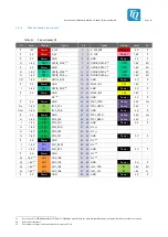
3.11
Reset structure
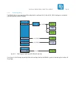
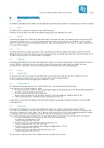
Figure 25 shows the reset structure on the MBa8Xx.
In addition to the reset signals of the TQMa8Xx, the MBa8Xx also provides further software-controlled reset signals for individual
function blocks, e.g. ENET reset for the Ethernet transceivers. These are implemented by GPIO signals and named accordingly in
the respective chapters when applicable.
TQMa8Xx
RESET_OUT#
IMX_ONOFF
PMIC_PWRON
V_1V8
10
kΩ
Level
Shifter
TUSB8041
GRST#
10
kΩ
PCA9538A
IO_5
NP
V_1V8
TLV320
RESET#
PCA9538A
RESET#
Header
(X5)
Power button
(S5)
On/Off button
(S6)
RESET_IN#
Reset button
(S4)
JTAG
(X15)
3-state
Buffer
V_1V8
10
k
Ω
Figure 25: Block diagram Reset
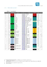
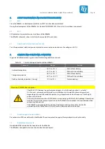
Table 52:
RESET_IN# (affects JTAG_SRST# at X15)
Parameter
Min.
Typ.
Max.
Remark
Input voltage
High level
Low level
1.2 V
–
1.8 V
–
5.5 V
0.6 V
Low-active
Table 53:
RESET_OUT# (at X5)
Parameter
Min.
Typ.
Max.
Remark
Output voltage
High level
Low level
1.2 V
–
–
–
1.84 V
0.5 V
Low-active


