User's Manual l MBa8Xx UM 0100 l © 2020, TQ-Systems GmbH
Page 13
Default I2C interface (continued)
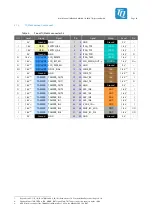
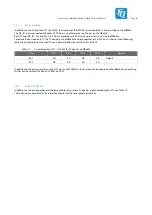
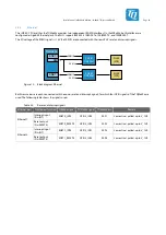
The following table shows the default I²C device addresses on the MBa8Xx and the TQMa8Xx.
For some devices the address can be changed by assembly options. The options are described in detail in the given chapter.
Table 10:
I
2
C devices, address mapping on TQMa8Xx and MBa8Xx
Location
Device
Function
7-bit address
Remark
TQMa8Xx
SE050
Trusted Secure Element
0x48 / 100 1000b
24LC64
EEPROM
0x57 / 101 0111b
SE97BTP
Temperature sensor
0x1B / 001 1011b
EEPROM
0x53 / 101 0011b
R/W access in Normal Mode
EEPROM
0x33 / 011 0011b
R/W access in Protected Mode
PCF85063
RTC
0x51 / 101 0001b
MBa8Xx
TUSB8041
USB hub (optional)
0x44 / 100 0100b
Optional
TLV320
Audio Codec
0x18 / 001 1000b
SN65DSI86
DisplayPort bridge
0x2C / 010 1100b
9FGV0241
PCIE clock generator
0x6A / 110 1010b
Optional
PCA9306DQE
Temperature sensor
0x1C / 001 1100b
Discrete
SE97BTP
EEPROM
0x54 / 101 0100b
R/W access in Normal Mode
EEPROM
0x34 / 011 0100b
R/W access in Protected Mode
PCA9538A
Port expander
0x70 / 111 0000b
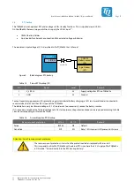
Note: I²C address conflicts
When changing the address due to assembly options or when connecting further I²C components,
it must be ensured that no address conflicts occur. Otherwise malfunctions may occur. The addresses
preassigned by the TQMa8Xx must also be observed (depending on the TQMa8Xx variant used).
10:
Only when using TQMa8Xx4 without assembled PCIe clock generator.

