


User's Manual l MBa8Xx UM 0100 l © 2020, TQ-Systems GmbH
Page 5
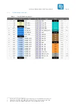
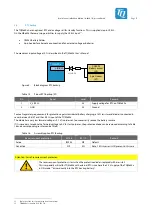
2.2
MBa8Xx data interfaces
The following interfaces/functions and user interfaces are available on the MBa8Xx:
Table 2:
Data interfaces
Interface
Connector
Type
Audio
X8
X9
X10
3.5 mm jack
•
MIC
•
Line-in
•
Line-out
CAN-FD
X11, X12
3-pin Phoenix
Coin cell
X6
CR2032 holder
eDP / DisplayPort
X23
20-pin, 90°
Ethernet, 1000 Base-T
X18, X19
RJ-45, integrated magnetics
Headers
X4, X5
100 mil header, 2 × 60-pin
LVDS (Dual)
X14
30-pin, DF19G
LVDS CMD
X22
20-pin, DF19G
MIPI CSI
X28
60-pin, Board-to-Board
Mini PCIe
X24
Mini PCIe socket
X25
SIM card holder
Power In
X26
DC jack (2.5 mm / 5.5 mm)
X27
2-pin screw terminal block
SD card, UHS-I
X17
Push-Pull
USB 2.0 Hi-Speed Host
X22, X24
20-pin, DF19G, Mini PCIe socket
USB 2.0 Hi-Speed OTG
X29
USB, Micro AB
USB 3.0 SS Host
X20
USB, stacked Type A
USB debug
X13
USB, Micro AB
The MBa8Xx provides the following diagnostic and user interfaces:
Table 3:
Diagnostic and user interfaces
Interface
Component
Remark
Status LEDs
9 × Green LED
Power LEDs
4 × Green LED
3 × USB Host, 1 × USB OTG
1 × Green LED
Debug LED for USB debug interface
2 × Green LED
GP LEDs at port expander
3 × Green LED
Mini PCIe: WWAN, WLAN, WPAN
1 × Red LED
Reset LED
2 × Green / Yellow LED
Ethernet LEDs (Activity / Speed)
Temperature sensor
1 × SE97BTP
Digital I
2
C temperature sensor
Power / Reset button
3 × Push button
RESET-IN, PMIC_PWRON, IMX_ONOFF
General Purpose button
2 × Push button
GP push button at port expander
Boot Mode configuration
1 × 4-fold DIP switch
Boot Mode configuration
CAN termination
2 × 2-fold DIP switch
–
JTAG
1 × 20-pin, 100 mil header
–


