background image

      26

Gigabit Uplink Web Smart Switch 

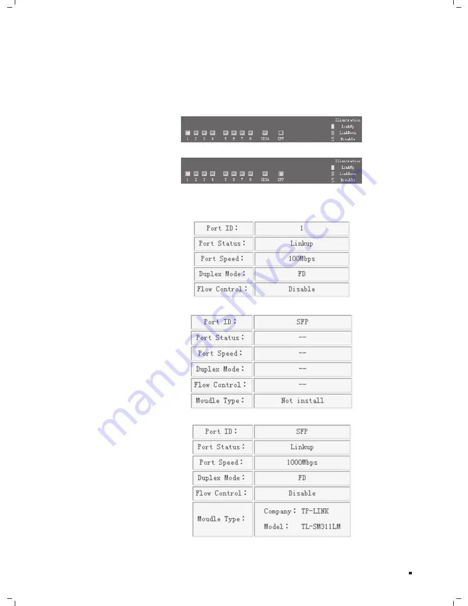
The  Port  LED  Indicator  table  lies  at  the  top  of  the  page.  It  provides  a  visual 

2. 

representation of the ports on the switch front panel to display the status of the 
ports. The ports, signed with number are the normal ports, signed with GIGA are the 
Giga ports, signed with SFP are the SFP ports. The green icon indicates that the port 
is linked; the gray icon indicates that the port is not linked; a gray icon with a black 
bar indicates that the port is disabled; for the SFP port, a blue icon indicates that the 
SFP module hasn’t been installed.

Port LED Indicator Table (SFP uninstalled1

Figure 6-8 

Port LED Indicator Table (SFP installed1

Figure 6-9 

Click on the icon of the port to open a new window, which shows the details of the port, 
as shown below:

Port Status Table

Figure 6-10 

SFP Status Table (uninstalled1

Figure 6-11 

SFP Status Table (installed1

Figure 6-12 

Web Management

Summary of Contents for TL-SL2210WEB

Page 1: ...User Guide Gigabit Uplink Web Smart Switch TL SL2210WEB TL SL2218WEB TL SL2428WEB TL SL2452WEB Enterprise Networking Solution...

Page 2: ......

Page 3: ...ent This equipment generates uses and can radiate radio frequency energy and if not installed and used in accordance with the instruction manual may cause harmful interference to radio communications...

Page 4: ...to install the Switch Chapter 3 Lightning Protection This chapter illustrates how to prevent lightning damage Chapter 4 Connection This chapter illustrates how to do the physical connec tion of the Sw...

Page 5: ...3 Lightning Protection Chapter 4 Connection and Chapter 6 WEB Management This Guide uses the specific formats to highlight special messages The following table lists the notice icons that are used th...

Page 6: ...Connection 13 4 1 Ethernet Port 13 4 2 SFP Port 13 4 3 Verify Installation 14 4 4 Power On 14 Chapter 5 Function Description 15 5 1 System Setting 15 5 1 1 System Setting 15 5 1 2 File Transfer 15 5 1...

Page 7: ...ew 22 6 2 Connecting to the Device 22 6 2 1 Getting Started 22 6 2 2 Login the Switch 25 6 3 Setting the Device 25 6 3 1 System Setting 28 6 3 2 Port Setting 30 6 3 3 Network Setting 35 6 3 4 VLAN Set...

Page 8: ...onnecting area and increases the networking flexibility Features 1111 Compliant with IEEE802 3 IEEE802 3u IEEE802 3ab and IEEE802 3z Standards IEEE 802 3x flow control for full duplex Back pressure fl...

Page 9: ...0 22 24 SFP 1 Power 1 3 5 7 9 11 13 15 17 19 21 23 GIGA1 2 4 6 8 10 12 14 16 18 20 22 24 GIGA2 System 100M 1000M SFP 2 Act Link SFP 2 SFP 1 Reset TL SL2428WEB 24 4G Gigabit Web Smart Switch Front Pane...

Page 10: ...100Mbps Off There is no device linked to the corresponding port or the port is running at 10Mbps 1000Mbps On The corresponding port is running at 1000Mbps Off There is no device linked to the correspo...

Page 11: ...wn as the following figure Rear Panel FFFFFFFFFFF Power Socket Connect the female connector of the power cord here and the male connector to the AC power outlet Please make sure the voltage of the pow...

Page 12: ...Safety Precautions 2222 To avoid any device damage and bodily injury caused by improper use please observe the following rules Safety Precautions Keep the power off during the installation Wear an ES...

Page 13: ...eb Smart Switch Power 100M Link Act System 1000M GIGA Link Act Link Act R The dust accumulated on the Switch can be absorbed by static electricity and result in poor contact of metal contact points So...

Page 14: ...nd device are well earthed Make sure the power socket has a good contact with the ground Keep a reasonable cabling system and avoid induced lightning Use the signal SPD Surge Protective Device when wi...

Page 15: ...r the device and attach the supplied rubber feet to the recessed areas on 333 the bottom at each corner of the device 1 3 5 7 2 4 6 8 GIGA SFP 10 10 0Mbp s 10 100 1000Mb ps 1000M bps 1 2 3 4 5 6 7 8 T...

Page 16: ...ure the brackets to the rack as illustrated in the following figure 1 3 5 7 2 4 6 8 GIGA SFP 10 100 Mbps 10 100 10 00Mbps 1000M bps 1 2 3 4 5 6 7 8 TL SL2210WEB RESET 8 2G Web Smart Switch Power 100M...

Page 17: ...s should be buried and paved to the indoor through basement A piece of steel wire should be paved underground along the pipe and connected to the lightning protection terminal of the building for shie...

Page 18: ...overlapping Net Height H mm1 Down conductor 1000 300 PE 50 20 Service pipe 150 20 Compressed air pipe 150 20 Thermal pipe not wrapped1 500 500 Thermal pipe wrapped1 300 300 Gas pipe 300 20 The two di...

Page 19: ...is also a necessary measure to protect the body from electric shock In different environments the device may be grounded differently If the device is installed in the normal environment the device ca...

Page 20: ...444 Connect the SFP port to a SFP module If an SFP transceiver purchased separately is installed in a slot and has a valid link on the port the associated RJ45 port will be disabled and cannot be used...

Page 21: ...and rack are well grounded The device is correctly connected to other network devices Power On 4444 Plug in the negative connector of the provided power cord into the power socket of the device and t...

Page 22: ...unction of configuration backup configuration loading and system upgrading The configuration file and executive file are transferred in TFTP protocol TFTP Trivial File Transfer Protocol is dedicated t...

Page 23: ...dcast frames it has received and so on Port Status indicates whether the port is linked not linked or disabled what speed and duplex mode it is working on and whether flow control is enabled or disabl...

Page 24: ...switch firstly then the switch will automatically obtain IP address netmask and default gateway from the DHCP server If more than one DHCP servers are available in the network the switch will choose...

Page 25: ...address excludes a device from being accessed through the switch All the packets taking the filtering MAC address as their destination will be discarded The filtering MAC address is applicable to all...

Page 26: ...h any other logical connection combination since they are software based and not defined by physical attributes VLANs function at Layer 2 Since VLANs isolate traffic within the VLAN a Layer 3 router w...

Page 27: ...ing the Trunk its member ports should be divided to the same VLAN and have the same PVID and drop untagged frame rule Change of the Trunk setting will not affect the VLAN setting Trunks can not be set...

Page 28: ...5 Port mirroring monitors and mirrors network traffic by forwarding copies of incoming and outgoing packets from one port to a monitoring port Port mirroring enables switch performs monitoring Network...

Page 29: ...er Due to the difference of parsing syntax the WEB page shows may differ between variable WEB browsers Microsoft Internet Explorer of version 5 0 or higher is recommended If Netscape is selected pleas...

Page 30: ...option Every visit to the page otherwise some wrong information may show in WEB pages If the IE version is 6 0 Every visit to the page or Automatically are both appropriate Click the OK button and co...

Page 31: ...FFFFFFFF Fourthly Select the Medium option of the combo box indicated in Figure 6 4 click the Reset button and click OK to quit Fifthly right click the mouse on desktop select the Display Properties i...

Page 32: ...r http 192 168 0 1 in the address location and then the following dialog page appears Login Dialog FFFFFFFFFFF Enter username and password default value are both supervisor to login the switch configu...

Page 33: ...at the port is linked the gray icon indicates that the port is not linked a gray icon with a black bar indicates that the port is disabled for the SFP port a blue icon indicates that the SFP module ha...

Page 34: ...and User Port Setting Port Parameter Port Statistic Port Status Storm Control and Port Description Network Setting Switch IP Address Static MAC Address Filtering MAC Address Dynamic Binding Bound MAC...

Page 35: ...FFF TL SL2452WEB Main Page FFFFFFFFFFFF System Setting 666666 System setting contains four topics system information file transfer reboot reset and user System Information 66666666 This page contains...

Page 36: ...r Type Lists three types of file transfer supported by the switch File Name Identifies the file to be loaded or to be backed up on TFTP server TFTP Server IP Indicates the IP address of TFTP server Fu...

Page 37: ...rovides the interface of configuring username and password User Configuration FFFFFFFFFFFF You are suggested to retype the new password in Confirm new password box instead of copying in order to avoid...

Page 38: ...rn new MAC address Caution If you haven t set the static MAC address you can t enable all of the port security which will result in an inability to manage the switch Flow Control Indicates whether the...

Page 39: ...ddress Rx Mcast The number of frames received that have a multicast destination MAC address Rx Bcast The number of frames received that have a broadcast destination MAC address Rx B Bytes The sum of b...

Page 40: ...rs Note Each statistic counter has the max numerical value of about 1 8e 19 in excess of this value the counter will be reset to zero You can also click on the Reset button to reset all of the statist...

Page 41: ...ximum rate kilobytes per second at which the controlled packets configured above are forwarded For the 1000Mbps port if set the value of 64Kbps the actual value is about 70Kbps Note Parameters of Trun...

Page 42: ...e three items should be configured manually IP Address Is necessary for switch management The configuration of switch IP address must be compliant with the subnet layout Default Gateway Serves as the...

Page 43: ...in enabled state or disabled state Operation Provides the function of enabling disabling or deleting an entry Return Return to the Static MAC Address page A searching can be also executed in this pag...

Page 44: ...uting to the device cannot reach the device A MAC address cannot be added to static MAC address table and filtering MAC address table simultaneously Filtering MAC Address 66666666 All the packets taki...

Page 45: ...s page If the dynamic binding is disabled or the switch restarts the bound MAC address entries are cleared There are 5 items in this page Dynamic Binding FFFFFFFFFFFF Port Indicates switch port number...

Page 46: ...lly in Port Parameter page the dynamic binding cannot be configured here If the port with dynamic binding enabled transfers into secure state automatically because the port has bound the specified num...

Page 47: ...of time that MAC address will be removed from the MAC address table This process is called aging and the specified time length referred above is called aging time Further explanation The aging time r...

Page 48: ...interval between two continuous pings VLAN Setting 666666 VLAN Mode 66666666 This page selects the VLAN Mode and possible field values are VLAN Mode FFFFFFFFFFFF VLAN Disable Do not set any VLAN in th...

Page 49: ...s of the VLAN Submit Submit to buildup a VLAN with the selected members Note Any VLAN cannot be the subset or superset of other VLANs At least two port members should be included to add a VLAN group I...

Page 50: ...e using the PVID of the port as its VID Untag Frame The solution to the untagged frame received Drop will drop the frame and Pass will transmit the frame in the VLAN with the VID the same as the PVID...

Page 51: ...VLAN here If this field is checked it indicates the port belongs to the current VLAN Egress Frame The solution to the egress frame Drop Tag indicates drop the tag header before sending the frame Add...

Page 52: ...et a default VLAN which is indexed as NO 1 and contains all switch ports will be built up The ports haven t been assigned to any VLAN manually cannot communicate with each other or other VLAN That s d...

Page 53: ...ins 2 to 4 ports If a Trunk is submitted with 0 member port it indicates to delete the Trunk SFP and 1000Mbps port in TL SL2210WEB TL SL2218WEB TL SL2428WEB TL SL2452WEB is not able to be the Trunk me...

Page 54: ...lowest lower higher and highest All the packets entering from the port of the switch are forwarded in the correspondingpriority queue Further explanation When priority rule is configured as weighted a...

Page 55: ...Further explanation In IEEE802 1p priority mode when a switch port receives an untagged frame a frame without priority tag the port s default priority tag will be inserted into the frame before any ot...

Page 56: ...t Virtual Cable Test 666666 The virtual cable test feature enables you test the continuity of the cable circuit It contains the following fields Virtual Cable Test FFFFFFFFFFFF Test Port Select the po...

Page 57: ...ld I do if I could not access the web based configuration QQQQ page You are recommended to check the following items Check every port LED on the Switch and make sure the cable is installed 111 properl...

Page 58: ...eter Port Status Enable Port Security Disable Flow Control Disable Duplex Mode Auto Port Statistic All 0 Storm Control Broadcast Control Disable Multicast Control Disable UL Control Disable Limit Rate...

Page 59: ...is Drop Tag MTU VLAN Setting Uplink port 1 Port Trunking No configured Trunk Priority Setting Priority Mode Priority Mode Disable Priority Rule Weighted Port Based Priority Priority Class Lowest Port...

Page 60: ...ls TL SL2210WEB TL SL2218WEB TL SL2428WEB TL SL2452WEB Port 10 18 28 52 Giga Port 2 2 4 4 SFP Port 1 1 2 2 Trunk 2 4 6 8 Port VLAN 10 18 28 52 Tag VLAN 64 64 128 256 Static MAC 64 128 128 128 Filterin...

Page 61: ...00Base TX UTP STP of Cat 5 or above 1000Base X MMF or SMF SFP Module Optional1 Safety Emissions FCC CE Transfer Method Store and Forward MAC Address Learning Automatically learning automatically aging...

Page 62: ...ysia Tel 1300 88 875465 1300 88TPLINK1 Email support my tp link com Service time 24hrs 7 days a week Turkey Tel 444 19 25 Turkish Service1 E mail support tr tp link com Service time 9 00 AM to 6 00 PM...

Page 63: ......

Page 64: ...Website http www tp link com E mail support tp link com 7106503690 Rev 2 0 0...

Reviews: