10
Redundant Power Supply
Connect to the Powered Device
111
The RPS150 can be used as a redundant backup power supply unit for multiple switch
models. Follow the steps below to connect the RPS150 to a powered device.
Confirm that the power supply of the RPS150 is cut off.
1.
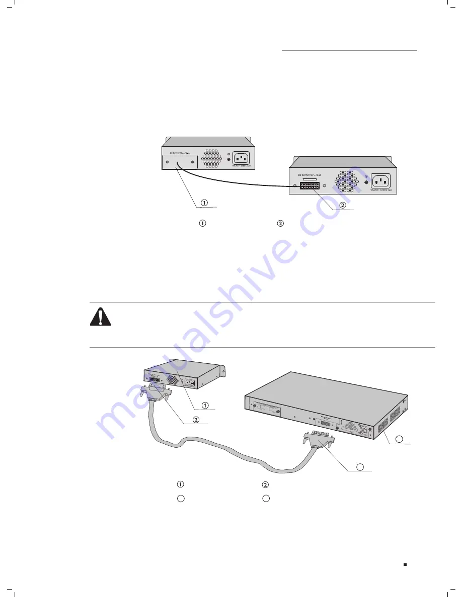
Remove the protective covers covering the redundant power socket of RPS150 and
2.
the switch. Here we take the removing process of RPS150 for example:
Removing the Protective Cover
Protective Cover
RPS DC Output
Removing the RPS Protective Cover
Figure 3-2
Connect the RPS150 and the switch with DC power cord, as illustrated in Figure 3-3.
3.
One end of the DC power cord is marked by the letters “TOP” and the other end has
a positioning card attached to it. Plug the end with the letters “TOP” into the input
socket of the switch with “TOP” facing up and the other end with positioning card
into the DC output socket of the RPS150 with the positioning card facing up.
Caution:
Make sure the power supply of RPS150 is cut off when connecting or disconnecting
RPS150 and the switch, otherwise both RPS150 and the switch may work abnormally
or even be damaged.
RPS INPUT
TOP
RPS INPUT
TOP
4
RPS150
Positioning Card
Switch
One connector with letters “TOP”
3
4
3
M1
SFP+
M2
SFP+
CLASS 1 L
ASER PRODUCT
TX432
Module
Power
PS OK
Fault
PSM150-AC
100-240V~ 50/60Hz 2.5A
Connecting to the Powered Switch
Figure 3-3
Connection


