background image

-  - 

57 

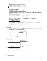
1)    When indoor coil temperature is lower than 5


go back to initial action, when this do not meet, the unit 

continue. When the fan stops in the beginning time of heat mode or working in low air speed more than 30 minutes, 

it will indicates trouble of outdoor, and all relay turn off.


       2)  When outdoor unit trouble inspection is not asked,   

4.2


The compressor control

:


4.2.1    Compressor 3 minutes protection: the same as cooling mode 

4.2.2    The compressor runs when Ta is lower than Ts, when Ta is equal or higher than Ts, the compressor stops. 

4.2.3    When in inspection function, the compressor stops.   


4.2.4  Over heat protection:   


        Start-up condition: when the compressor have been in working for 2 minutes, if indoor coil temperature is equal 

or higher than 70

, over heat protection runs. 


Over heat protection: the compressor stops for 6 minutes, indoor fan works in super low flow mode, then restart, 

indoor fan works in low flow mode, if within 10 minutes, the indoor coil temperature is equal or higher than 70


again, the unit shuts down and indicator trouble.     


4.3  Indoor fan control

:


indoor fan is control by set temperature, room temperature and indoor coil temperature. 


   Action of indoor fan:   

      1)  When room coil temperature is lower than 26

, indoor fan don't run. 

          2)    When room coil temperature is lower than 35

, indoor fan works in weak flow for 5 minutes, low air flow for 2 

minutes, and then works as the set air speed. 

3)    When room coil temperature is equal or higher than 35

, indoor fan works in low air flow for 2 minutes, and 

then works as the set air speed. 

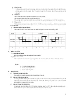
            Heating period after the running of the fan: (Tc = indoor coil temperature    Ta = room temperature) 

                    When the difference of Tc and Ta reduce from 

5

 to -5

℃<

Tc-Ta

5

, the fan remain the pre air flow, if 

the air speed change, the air flow can only be reduced, the electricity heat shuts down. 

              1)    When 0

Tc-Ta

3

, electrical heater shuts down for more than 1 minute, indoor fan stops, otherwise the 

fan speed changes to low flow. 

              2)    When Tc -Ta 

0

, indoor fan stops.       


3)    When Tc -Ta 

-5

, goes into dehumidifying mode. 

                  When  Tc  –  Ta 

5

  again, if the fan is in static state, it goes into heat starting process, if the fan is in 

working, and the electrical heater shuts down not more than 1 minute in -5

℃<

Tc-Ta

5

, the fan speed 

don't change, if it is changed, it can only be reduced. In other conditions, the fan speed works as set air 

speed. 


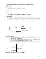
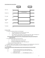
4.4  Swing louver control

: working action is the same as in cooling mode.   

4.5  Electrical heater control

       Start–up conditions: (all following conditions meet)  

            Tc - Ta 

5

; Ts – Ta 

3

; Ta 

23

; indoor coil temperature 

55

; electrical heater have been shut down 

for 1 minute in -5

℃<

Tc-Ta

5

, and not in hot starting process, electrical heater can still run.   

      Stop conditions: (one of following condiiton)  

Tc - Ta 

5

; Ta = Ts; Ta 

26

; Tc 

60

.


 4.6  Clear spare heat function

:   


After the electrical heater’s shutting down, indoor fan works in low flow for 30 seconds, and then stops. 


4.7  Dehumidifying control

: (see outdoor unit control) 


Summary of Contents for TA-05CW

Page 1: ...CONTROL SYSTEM 4 WIRING DIAGRAM 22 4 REFRIGERANT FLOW CHART COOLING COOLING HEAT MAXIMUM LENGTH OF REFRIGERANT PIPE 5 MICROPROCESSOR CONTROL MICRO PROCESSOR CONTROL ELECTRIC CONTORL SECTION 1 Main Parts Introduction 1 1 Compressor The compressor which is controlled by contactor will in turn make it act through relay when Main chip output is high level Auxiliary start up function when the compresso...

Page 2: ...ain frame receives remote Start up signal It will buzz once for 1 second when receiving turn off signal It will buzz for 0 5 second once receiving other signal It will not buzz when receiving abnormal signal 1 5 Indicator There are 4 indicators operating indicator water level warning indicator defrosting indicator and pre heating indicator wind delivery indicator for cooling only A C The light emi...

Page 3: ...able auto swing function and all direction airflow distribution 5 Equipped with world famous rotary compressor and heat exchanger made by inner grooved copper tube and hydrophilic aluminum fins high efficiency and energy saving 6 Detachable front panel and air filter easy to clean 7 Three minute restart delay protection 8 Freon free refrigerant R407c is adopted for environmental protection Part 1 ...

Page 4: ...Maximum dB A 47 50 50 52 52 Net weight Kg 21 36 36 46 46 Grass weight Kg 23 38 38 50 50 R22 g 380 700 700 800 820 Refrigerant type Quantity R407C g 380 700 700 800 820 Suction pressure Mpa 1 2 1 2 1 2 1 2 1 2 Discharge pressure Mpa 2 8 2 8 2 8 2 8 2 8 Width mm 470 445 445 560 560 Depth mm 350 605 605 650 650 Dimension Height mm 310 350 350 400 400 Width mm 565 705 705 735 735 Depth mm 456 540 540 ...

Page 5: ...56 56 57 Net weight Kg 56 56 58 58 Grass weight Kg 60 60 62 62 R22 g 1080 1150 1300 1730 Refrigerant type Quantity R407C g 1040 1110 1250 1660 Suction pressure Mpa 1 2 1 2 1 2 1 2 Discharge pressure Mpa 2 8 2 8 2 8 2 8 Width mm 705 705 705 705 Depth mm 670 670 670 670 Dimension Height mm 455 455 455 455 Width mm 760 760 760 760 Depth mm 732 732 732 732 Packing Height mm 490 490 490 490 Shockproof ...

Page 6: ...ng wind 2 Low Fan button is selected the fan motor operates with low speed and sends out the breeze wind 3 Mid Fan button is selected the fan motor operates with mid speed and sends out the mid wind 4 High Cool button is selected the air conditioner is cooling quickly and sends out the strong cool wind 5 Low Cool button is selected the air conditioner is cooling at mid speed and sends out the mid ...

Page 7: ...N yellow green Compressor BU Capacitor YE GN GN BU WH RD S Operation 2 TA 07CW TA 09CW N Blue Brown Brown OFF Thermostat Red S C Low Fan High Fan High Cool Low Cool L 1 3 Operation 0 4 2 Red Yellow Green Blue Blue MS Step Motor Switch Capacitor Fan Motor Brown Black Blue Blue 1 Step Motor Red Blue Blue Brown Yellow Yellow Green C Capacitor Yellow Green Compressor Plug Yellow Green Blue R Blue L Bl...

Page 8: ...ellow Y G yellow green Y G Y G 4 TA 16CW TA 18CW TA 24CW BN BU L BN Plug BK Compressor BU BU BN RD Capacitor BU S Y G BU R C Y G Fan Motor Synchronous Motor 1 Thermostat C Operation L BN 3 BU OFF High Cool High Fan Low Cool Low Fan RD 2 YE 1 OR 4 MS OR Synchronous Motor Switch 0 BU N BN brown BU blue BK black RD red OR orange YE yellow Y G yellow green Y G Y G Note The wire diagrams could change w...

Page 9: ...ling and mild dehumidifying 4 2 step fan speed adjustable auto swing function and all direction airflow distribution 5 Equipped with world famous rotary compressor and heat exchanger made by inner grooved copper tube and hydrophilic aluminum fins high efficiency and energy saving 7 Detachable front panel and air filter easy to clean 8 Three minute restart delay protection 9 Freon free refrigerant ...

Page 10: ...sion Height mm 250 199 240 Width mm 810 810 856 1050 Depth mm 242 320 342 367 Indoor packing Height mm 320 242 290 246 Indoor net weight Kg 8 8 8 5 14 Indoor gross weight Kg 11 11 11 17 Outdoor noise level dB A 49 46 50 50 Width mm 700 700 798 Depth mm 270 270 260 Outdoor Dimension Height mm 545 545 528 Width mm 768 768 922 924 Depth mm 334 334 322 324 Outdoor packing Height mm 590 590 592 592 Out...

Page 11: ...240 238 Width mm 856 906 Depth mm 342 375 Indoor packing Height mm 290 31 7 Indoor net weight Kg 8 5 18 Indoor gross weight Kg 11 21 Outdoor noise level dB A 50 52 Width mm 798 798 Depth mm 260 260 Outdoor Dimension Height mm 528 528 Width mm 924 959 Depth mm 322 392 Outdoor packing Height mm 592 757 Outdoor net weight Kg 44 69 Outdoor net weight Kg 52 79 R22 g 1500 2200 Refrigerant type Quantity ...

Page 12: ...3 When 9 Ta Ts 4 indoor fan works as following chart High wind Middle wind Low wind 0 2 4 Ta Ts 4 Indoor fan motor speed Strong 1320 r min High 1260 r min Middle 1150 r min Low 960 r min Breeze 600 r min Economic 840 r min Remarks Different models maybe be different about fan motor speed The speed is for reference only 5 Continued working function in Cooling Mode When Ts is less than 18 or more th...

Page 13: ... s working 7 Preventing Indoor coil frost in cooling mode 1 Indoor coil temperature is 1 and the compressor has been in working for 6 minutes already turn off compressor and indoor fan motor changes into low flow mode 2 Indoor coil temperature is 8 and the compressor has already been off more than 3 minutes restart the compressor indoor fan motor works as it is set 8 Compressor and outdoor fan con...

Page 14: ... automatically 二 二 二 二 Dehumidifying mode 1 Set temperature 18 30 2 First usage of dehumidifying mode the indoor fan motor will works in low flow mode for 20 seconds and begin to work relative to the room temperature Four working period Ta room temp Ts set temp A Ta Ts 3 B Ts 3 Ta Ts C Ts Ta Ts 2 D Ts 2 Ta 1 Begin to operate Compressor ON A B Period Outdoor fan motor OFF Indoor fan motor ON Set fa...

Page 15: ...nd begin a new circle Compressor ON A Period B Period Outdoor fan motor OFF 30 s 30 s Low flow ON Indoor fan motor OFF 0 4 8 0 4 8 minutes Compressor ON D Period C Period Outdoor fan motor OFF 30 s 30 s Low flow ON 30 s Indoor fan motor OFF 0 4 8 0 4 8 minutes Continued working function in Dehumidifying Mode Continued Dehumidifying mode function CONT is similar as the Continued Cooling mode when i...

Page 16: ...ontinued working function in Fan Mode 1 Independent with the Ta and Ts send out flow forcibly 2 When the remote control is set as AUTO or HI mode the indoor fan motor works in middle flow mode or high flow mode when the remote control is set as LO mode the indoor fan motor works in low flow mode 6 Swing louver action in Fan Mode The procedure is similar with the working procedure in Cooling Mode b...

Page 17: ...ing mode indoor fan motor can be set as AUTO HI MID LO modes 7 Continued working function in Heat Mode When Ts is lower than 18 or higher than 30 CONT is shown on remote control the unit goes into continued working period 1 The compressor and outdoor fan motor runs the reversing valve is connecting heating forcibly 2 When the remote control is set as AUTO or HI indoor fan motor works in high flow ...

Page 18: ... 5 second off for 0 5 second 10 Over heat of the indoor coil protecting in Heating mode 1 When the temperature of the indoor coil is equal 55 the temperature of the indoor coil is equal 55 no matter what Ta is indoor fan changes to high flow mode and the outdoor fan will be off The outdoor fan will not be on until the temperature reduce to 48 2 When the temperature of the indoor coil is equal or h...

Page 19: ...g cooling in auto mode 1 hour before the auto run time detect the room temperature automatically decide when to run with the difference between the room temperature and the set temperature Ta Ts Ahead of time 0 2 5 minutes 2 10 15 minutes 11 15 30 minutes 15 60 minutes 七 七 七 七 LED display 1 When the unit is switched on the green LED is on and green LED will be off when the unit is off 2 On timer f...

Page 20: ...rflow supply and run for 30 seconds first then identify the most suitable operation mode such as cooling dehumidifying or heating etc 十 Self diagnosis function If the air conditioner starts work from the emergency button the unit goes into the self diagnosis period The buzzer will buzz once and the indoor fan runs all the lighting tubes light after 2 seconds the lighting tubes are off and outdoor ...

Page 21: ...1 BN BU YE GN BN BN brown BU blue YE GN yellow green TO OUTDOOR UNIT Coil Sensor Room Temp Sensor Outdoor Unit To Indoor Unit YE GN WH Outdoor Motor Compressor Running Capacitor OUTDOOR UNIT WIRING DIAGRAM ONLY COOLING BK OG S YE GN FM RD BN C CM RT BU Compressor R BU 1 BU 2 BN YE GN YE GN BN brown BU blue BK black WH white RD red OG orange YE GN yellow green 2 TA 09CHS TA 12CHS ...

Page 22: ...ire 3 BK TO OUTDOOR UNIT INDOOR UNIT WIRING DIAGRAM C OM EXF 4WF CN11 PRINT CIRCUIT BROAD Outdoor Unit BN H BN brown BU blue BK black WH white RD red OG orange YE GN yellow green Compressor Running Capacitor BU RD BU BN R C CM S Compressor RT YE GN OUTDOOR UNIT WIRING DIAGRAM 2 BK BN S BU YE GN 3 4 YE GN Fourway Valve OG BK FM WH BU BK BU BK Outdoor Motor YE GN To Indoor Unit 1 3 TA 16CS TA 18CS I...

Page 23: ...T BROAD Sensor 2 CN7 YE GN 4 2 CN6 3 CN11 CN9 12 CN12 CN13 SW1 2 1 N L BN BU BN BN COM NO AC N Fan Motor M M 1 Outdoor Unit YE GN Outdoor Motor RT OUTDOOR UNIT WIRING DIAGRAM YE GN BU Motor Capacitor WH RD OR FM YE GN Compressor RD S BN C CM BU R BU BN 1 2 BU Compressor Capacitor TO INDOOR UNIT 4 TA 16CHS TA 18CHS ...

Page 24: ...U BU BK RT YE GN BU R CM S 1 RD C Compressor 1 TO INDOOR UNIT 4 YE GN BN S BK 3 BU 2 BN H BU Outdoor Unit YE GN TO OUTDOOR UNIT CN7 PRINT CIRCUIT BROAD BN brown BU blue BK black RD red YE yellow YE GN yellow green Room Temp Sensor M CN9 CN12 CN6 CN11 2 2 3 12 Stepmotor SW1 CN13 1 Fan Motor BN BU BN RD YE BU BK BN H BN S 2 4 3 1 BN L N NO 4WF CN8 COM AC N M EXF B SERIAL ...

Page 25: ... Room Temp Sensor CNE GB HW Rec eiver CNM CNW CNL M YE GN 1 BU BN YE GN 2 BU BN NO AC N BYQ CN FAN M COM CNA Outdoor Unit Motor Running Capacito r Compr essor BN R RT CM YE GN YE GN BK Outdo or Motor FM OR WH S C BU BN YE GN YE GN BU RD 1 2 TO INDOOR UNIT Compr essor Run ning Capa citor BU 2 TA 07CHS TA 09CHS TA 12CHS Indoor Unit ...

Page 26: ...Eme rgency Switch CNL Room Temp Sensor CNE Rece iver HW GB M 4WA Y VNW CNM CNA BYQ AC N CN FAN NO M COM Outdoor Unit Outdoor Motor OUTDOOR UNIT WIRING DIAGRAM BK WH OR CM RT YE GN FM YE GN Fourway Valve S C Motor Running Capacitor YE GN BU BU RD BN BU TO INDOOR UNIT 3 BU 4 YE GN 1 BK 2 BN S BN H Compressor Running Capacitor Compressor BU R 3 TA 16CS TA 18CS Indoor Unit ...

Page 27: ...D Sensor 2 CN7 YE GN 4 2 CN6 3 CN11 CN9 12 CN12 CN13 SW1 2 1 N L BN BU BN BN COM NO AC N Fan Motor M M 1 Outdoor Unit YE GN Outdoor Motor RT OUTDOOR UNIT WIRING DIAGRAM YE GN BU Motor Capacitor WH RD OR FM YE GN Compressor RD S BN C CM BU R BU BN 1 2 BU Compressor Capacitor TO INDOOR UNIT 4 TA 16CHS TA 18CHS Indoor Unit ...

Page 28: ... RT YE GN BU R CM S 1 RD C Compressor 1 TO INDOOR UNIT 4 YE GN BN S BK 3 BU 2 BN H BU Outdoor Unit YE GN TO OUTDOOR UNIT CN7 PRINT CIRCUIT BROAD BN brown BU blue BK black RD red YE yellow YE GN yellow green Room Temp Sensor M CN9 CN12 CN6 CN11 2 2 3 12 Stepmotor SW1 CN13 1 Fan Motor BN BU BN RD YE BU BK BN H BN S 2 4 3 1 BN L N NO 4WF CN8 COM AC N M EXF B1 SERIAL ...

Page 29: ...p motor Room Temp Sensor M CN HW CNW CNM CNE1 SW Coil Sensor CN GB M NO CNA COM ACN BYQ COMP RLY1 C CN FAN N Transformer YE GN Outdoor Unit 2 To Indoor Unit Outdoor Motor FM YE GN BK OG WH YE GN YE GN Compressor Running Capacitor Compressor CM S YE GN RT RD BN R BU C BN brown BU blue BK black WH white RD red OG orange YE GN yellow green BU 1 BU BN 2 TA 09CHS ...

Page 30: ...NIT WIRING DIAGRAM YE GN YE GN To Outdoor Unit Power Plug Line BU BN H BN S 2 BK 3 RD 1 BN BU YE YE GN BN 4 BU L BK BN BU N WH Outdoor Unit RD FM Outdoor Motor YE GN WH OG YE GN S Fourway Valve BK BU BK BU BK BN To Indoor Unit YE GN 2 3 4 BU 1 BN S YE GN BK BU BN H OUTDOOR UNIT WIRING DIAGRAM Running Capacitor Compressor CM C RT Compressor R BU BN brown BU blue BK black WH white RD red OG orange Y...

Page 31: ...U BN N L YE GN Receiver Coi l Sens or DIS P AC N Tra nsfo rmer BU TRA NS AC L COM P M FAN MD FFB Dis play IR TO OUTDOOR UNIT M Outdoor Unit RD BU BN BU 2 BN 1 BU FM Out door Mot or YE GN Mot or C apac itor WH BK OR YE GN YE GN Compressor Running Capacitor RT YE GN Com pres sor C R S CM 4 TA 12CHS TA 18CHS Indoor Unit ...

Page 32: ...o rmer BU AC L 4V TRA NS COM P FAN OF M Ste pmot or BN S BK BK RD Coi l Sens or MD IR Receiver DIS P FFB Dis play M Outdoor Unit BU 2 1 BN H BU BN S 3 4 YE GN BK C Compressor Compressor Running Capacitor YE GN S FM Outdoor Motor Fourway Valve RT YE GN YE GN Motor Capacitor R CM WH OR BK BU BK BU BK BU RD BN 5 TA 24CS Indoor Unit ...

Page 33: ... Stepping Motor Stepping Motor Reciving Indicator Air Anion Utraviolet Light Tube Fresh Function in dash line frame Note Special Utroviolet Killing germ and Air Anion Outdoor Unit Outdoor Motor FM CM BU BU WH 4 L BN YE GN Connect to Indoor Unit L BN 2 N BU 3 1 C BK YE GN YE GN N BU 5 RD Fan Motor Capacitor BN BU BK BU BN AC Contactor BK BU BU Comp Capacitor RD BN Compressor YE GN YE GN 6 TA 24CHS ...

Page 34: ...ping Motor M RD YE BK YE GN 1 2 3 BN BU N L Indoor PG Motor M In doo r Motor In dic ator 4 way Valve Outdoor Motor Compressor L N Ma in C ontrol Board Re civ ing BK YE RD YE GN BU BN Outdoor Unit Connect to indoor unit Black F 1 N L V C 2 3 4 5 Blue BN BU Capacitor Fan Motor L N BU YE GN FM RD Outdoor Fan Motor WH BU Blue Brown Reversing Valve BU BN BU Compressor Capacitor RD BU YE GN CM Compresso...

Page 35: ...XE 4WAY COM NO AC N C N F A N Stepmotor M M Coil Sensor GB INDOOR UNIT WIRING DIAGRAM YE GN Indoor PG Motor Outdoor Unit BU Running Capacitor YE GN CM Outdoor Motor YE GN S RT FM YE GN BU Motor Running Capacitor Compressor R C RD YE Compressor BN BU RD BN brown BU blue YE yellow RD red YE GN yellow green To Indoor Unit 1 BU BN YE GN 3 2 2 TA 07CHS TA 09CHS Indoor Unit ...

Page 36: ...eceiver C N F A N M Indoor PG Motor VNW CNM M Outdoor Unit BN brow n BU blue YE yellow RD red YE GN yellow gree n BK bla ck Running Capacitor Fourway Valve CM Outdoor Motor FM YE GN S YE GN RT RD Motor Running Capacitor BU BU BK BU BK BN RD BU R YE Compressor BU TO INDOOR UNIT BN H BK BU BN S 3 4 2 1 YE GN OUTDOOR UNIT WIRING DIAGRAN Compressor C H SERIAL ...

Page 37: ...or M FAN FFB PIPE ROOM SW DISP IR MD M AC N TRANS COMP Transformer AC L 2 BU BN N Y G 1 BU BN Y G BN TO OUTDOOR UNIT Outdoor Unit Compressor CM BN Outdoor Motor FM YE GN BK WH OG RT YE GN R S To Indoor Unit 1 YE GN BU YE GN 2 BU RD BU Running Capacitor BN Compressor C BN brown BU blue BK black WH white RD red OG orange YE GN yellow green 2 TA 07CHS TA 09CHS TA 12CHS TA 18CHS Indoor Unit ...

Page 38: ...Display PIPE Coil Sensor BN brown BU blue BK black RD red Y G yellow green M Stepmotor Outdoor Unit OUTDOOR UNIT WIRING DIAGRAM FM YE GN Outdoor Motor OG WH C YE GN Fourway Valve BK CM RT S YE GN BN brown BU blue BK black WH white RD red OG orange YE GN yellow green Compressor BN H BN BU BK BU BK 2 BK 1 BN S BU YE GN 3 4 Compressor Running Capacitor RD BU R BU To Indoor Unit K1 K2 SERIAL 1 TA 07CS...

Page 39: ... To Outdoor Unit YE GN BU BN YE GN N BU L BN WH BK CNW CNM SW BN BN 1 ACN BYQ NO COMP RLY1 CNA COM Stepmotor M Outdoor Unit YE GN BU YE GN 2 BU RD BU Running Capacitor BN Compressor C BN brown BU blue BK black WH white RD red OG orange YE GN yellow green Compressor CM BN Outdoor Motor FM YE GN BK WH OG RT YE GN R S To Indoor Unit 1 2 TA 07CHS TA 09CHS TA 12CHS Indoor Unit ...

Page 40: ...N A RD EXF C CN FAN N SW CNW M CNM A CN NO CO MP 4WV BY Q M INDOOR UNIT WIRING DIAGRAM Transformer Outdoor Unit OUTDOOR UNIT WIRING DIAGRAM FM YE GN Outdoor Motor OG WH C YE GN BK CM RT S To Indoor Unit YE GN BN brown BU blue BK black WH white RD red OG orange YE GN yellow green Compressor BN H BN BU BK BU BK 2 BK 1 BN S BU YE GN 3 4 Compressor Running Capacitor RD BU R BU Part 4 Trouble shooting ...

Page 41: ...temperature sensor On Flash one time per 8 seconds Failure in room temperature sensor On Flash one time per 8 seconds Failure in outdoor unit Flash five times per 8 seconds On Flash on 0 5 second off 0 5 second REMARK 1 FAILURE IN OUTDOOR UNIT WHEN COOLING 5 minutes after the close of the compressor relay If the indoor coil temperature keeps higher than 25 for 20 minutes running Meanwhile the timi...

Page 42: ... will be switched off automatically During the above mentioned process if the compressor relay has ever been off then time has to be counted from the moment the relay closes again 2 CAUSES OF THE FAILURE Refrigerant is not sufficient due to leakage The throttleable device is blocked up when cooling Something wrong with the indoor PCB board 三 三 三 三 FAILURE IN SENSORS 1 SYMPTOMS OF THE FAILURE There...

Page 43: ...air ensuring a cleaner and healthier living environment 4 Intelligentized auto mode and sleep mode operation function and 24 hours timer function 5 Mild dehumidifying auto defrosting and intelligentized temperature sensing 6 Over heat and over cold protection three minute restart delay protection 7 Cold airflow prevention function under heating anti frozen function under cooling And auxiliary elec...

Page 44: ...44 Part 2 Micro electric control system ...

Page 45: ...ndoor control main board 3 Controlled object 1 Indoor fan motor Fan motor Hi Mid Lo 2 Air flow direction 同步 motor 3 Compressor 4 Outdoor fan motor 5 Reversing valve 4 Data 1 Room temperature Ta 2 Evaporate temperature Te 3 Condenser temperature Tc 5 Description of the operation panel Power Air flow direction Air speed Indicator light Power indicator Green and Red On Timer indicator yellow Button O...

Page 46: ...e air conditioner goes into pre cooling mode the compressor and outdoor fan run the indoor fan run as the set air speed 3 When Ta Ts 1 C the air conditioner stops the compressor and outdoor fan stop too indoor fan still run as the set air speed b Dehumidifying Pre set 25 C 1 When Ta Ts 1 C the air conditioner goes into standard cooling mode 2 When Ta Ts 1 C the air conditioner goes into dehumidify...

Page 47: ...ing last more than 6 minutes defrosting ends the reversing and outdoor fan start to work indoor fan work regarding to anti cold wind function In defrosting period indicator light green flash 0 5 second off 1 5 seconds on e Auto mode 1 In auto mode indoor fan works in low flow mode for 20 seconds and then decide the working mode regarding to the room temperature 2 The relationship of the working mo...

Page 48: ...ng louver control Only if the indoor fan runs the swing louver control works 2 The buzzer control The controller start or receive the proper signal from the remote controller the buzzer will short buzz once Special a Forcible three short buzz b Power on two short buzz c Power off a long buzz 9 Protection a Compressor delay protection There will be a 3 minutes interval before the restarting of the ...

Page 49: ...s trouble in the indoor temperature sensor the compressor and outdoor fan and indoor fan stop e In auto fan mode works in mid flow mode f In auto mode works in forcible cooling mode air flow speed can change g If the trouble is overcome will restart automatically b Indoor temperature sensor trouble shooting In operation if indoor temperature sensor troubles the indoor timer light yellow flash as b...

Page 50: ...auto modes to choose 2 On timer function 3 Auto defrosting function 4 Set temperature range 18 30 5 Compressor restart 3 minutes delay protection 6 Auto flow high flow middle flow low flow to choose 7 Self diagnosis function 2 Control panel description 1 Panel introduction 2 Operation ...

Page 51: ... Timer and Temp set temperature is from 18 29 interval is 1 UP and DOWN button can be used to change the temperature or hour 3 Heat mode 1 If Ta is lower than Ts first start up or 3 minutes delay later the compressor runs if Ta is higher than Ts 3 the compressor will stop and begin 3 minutes delay function Compressor stop Compressor stop Ts 3 Ts Heat Heat Anti cold wind function Set fan speed Set ...

Page 52: ...n be choose in high flow middle flow and low flow modes This lead to strong cooling middle cooling and weak cooling Cooling Cooling Ts The compressor stops Ts 1 The compressor stops 5 Dehumidifying mode a When in dehumidifying mode the air conditioner will be in cooling mode until Ta Ts and then change into soft dehumidifying mode b When into soft dehumidifying mode the compressor and indoor fan w...

Page 53: ...l temperature 10 or 90 minutes outdoor coil temperature 8 or 120 minutes outdoor coil temperature 6 When dehumidifying function begins four way valve is off indoor fan stop the compressor works and indicator light is on 9 2 Defrosting will end when outdoor coil temperature is higher than 10 5 or continued working for 8 minutes The four way valve is on the air conditioner change back to heat mode 1...

Page 54: ...r Temp indicator flash Trouble indicator When trouble indication occurs the unit will stop press Power button the trouble indicator light will be off 13 Technology data 1 Power Main controller board 1ph AC220V 20 50Hz 1Hz Main control DC3V Voltage range 2 4 3 3V 2 controller working voltage range AC 220V 10 frequency range 50Hz 5 Compressor output controller AC 220V 10 frequency range 50Hz 5 Touch...

Page 55: ...perature control 18 29 2 2 Compressor control 2 2 1 3 minutes protection 1 3 minutes delay function of first usage of the compressor 2 3 minutes interval when restarting the compressor 2 2 2 When Ta is higher than Ts the compressor runs if Ta is equal or lower than Ts the compressor stops 2 2 3 When in inspection function the compressor stops 2 2 4 Anti indoor evaporate frosting function 1 when th...

Page 56: ...6 Over heat protection see page 47 outdoor unit control If outdoor coil temperature rise to 68 the indoor coil temperature will remain a lower temperature 7 12 3 Dehumidifying mode 3 1 Temperature control the same as cooling mode 3 2 The compressor control 3 2 1 Compressor 3 minutes protection the same as cooling mode 3 2 2 When in inspection function the compressor stops 3 2 3 When room temperatu...

Page 57: ...tes and then works as the set air speed 3 When room coil temperature is equal or higher than 35 indoor fan works in low air flow for 2 minutes and then works as the set air speed Heating period after the running of the fan Tc indoor coil temperature Ta room temperature When the difference of Tc and Ta reduce from 5 to 5 Tc Ta 5 the fan remain the pre air flow if the air speed change the air flow c...

Page 58: ...24 Flash means over heat protection 6 23 Flash means frozen protection 2 19 1 18 Light means trouble When Timer and Temp indicator flash and 1 18 2 19 indicator light when this happen the unit stops Press on off button trouble indicator is off 三 三 三 三 Outdoor unit control 1 Outdoor fan control Rotary frequency of outdoor fan is controlled by outdoor coil temperature This control way permits coolin...

Page 59: ...ON heat OFF Distributary ON 3minutes 3minutes valve OFF Outdoor ON Fan OFF 4 over heat protection in cooling mode Start up condition the compressor has been in working for 2 minutes if outdoor coil is higher than 68 the air conditioner is shut down and trouble showing Over heat protection the compressor stop for 3 minutes and then restart if the outdoor coil temperature is higher than 68 again the...

Page 60: ...conditions meet defrosting works 1 The compressor has worked for more than 7 minutes 2 Outdoor coil temperature is lower or equal than 5 3 The compressor s working time is more than defrosting interval Defrosting interval see Defrosting interval chart 3 When the working time of the compressor is more than defrosting interval the constant temperature unit restart for 3 times after 2 minutes of the ...

Page 61: ...n 2 When distributary valve is shut down the compressor stops distributary valve opens and last for 3 minutes Heat 1 First power on or the compressor open for more than 30 minutes and restart if outdoor coil temperature is equal or higher than 12 distributary valve open 2 When high pressure switch 63H1 works distributary valve opens 3 When distributary valve opens for 30 minutes if high pressure s...

Page 62: ...board with short circuit board J1 Reversal current inspection not inspection Inspection J2 side way valve control distributary valve defrosting switch open when distributary valve defrost J3 brace axis heat continue heating 1 hour off 1 hour on J4 cooling heat choose cooling heat cooling 5 service data display Through setting SW2 and SW3 lighting tube can display the output state and inspection co...

Page 63: ...H1 operation period 4 4 4 LD4 63H2 function Compressor runs 8 8 8 LD5 51C function Outdoor fan runs 16 10 10 LD6 26C function 4 way valve works 32 20 20 LD7 Over heat protect Distributary valve works 64 40 40 LD8 Input loop abnormal in controlled board Brace axis heater works 128 80 80 7 Outdoor coil temperature calculation Find out the outdoor coil CODE from about chart and then calculate as foll...

Page 64: ...separator Connceting pipe Refrigerant flow direction in cooling Capillary REFRIGERANT FLOW CHART 一 一 一 一 Cooling Only Pipeline Specifications Model Gas connecting pipe outer diameter mm Liquid connecting pipe outer diameter mm Capillary Dimension mm mm 9000 BTU cooling only 9 52 6 35 Φ1 37 850 12000 BTU cooling only 12 7 6 35 Φ1 62 900 18000 BTU cooling only 12 7 6 35 Φ1 80 750 Indoor unit Outdoor...

Page 65: ...alve Indoor temp thermistor Indoor coil thermistor Stop valve service mouth Refrigerant flow direction in cooling 二 二 二 二 Cooling heat Pipeline Specifications Model Gas connecting pipe outer diameter mm Liquid connecting pipe outer diameter mm Capillary 1 Dimension mm mm Capillary 2 Dimension mm mm 9000 BTU cooling heating 9 52 6 35 Φ1 37 850 Φ1 37 350 12000 BTU cooling heating 12 7 6 35 Φ1 62 900...

Page 66: ...ight difference 5m Maximum length of refrigerant pipe A It does not matter if the outdoor unit is in higher position Replenishment amount of refrigerant R 22 g Length of refrigerant pipe one way Model Profiled refrigerant for outdoor unit Max 7m 7m 10m 15m 9000 btu cooling only 900 12000 btu cooling only 800 18000 btu cooling only 1650 0 45 120 9000 btu cooling only 850 12000 btu cooling only 1150...

Page 67: ...er supply indication lamp is on Single chip is broken or the outside circuit is abnormal power supply A D transformer is broken or single chip has no output Check compressor start capacitor compressor Controllable silicon is broken or certain element or equipment outside is broken Relay is broken A D transformer is broken or single chip mount has no output Check if fan motor start relay has 12V vo...

Page 68: ...m temperature sensor Room temperature detecting 2 Indoor coil temperature sensor 3 Outdoor coil temperature sensor 2 4 Indication lamp board There are four kinds of indication lamps on the board They are economical powerful timing operation indication lamps HS 0038 signal receiver receives signals then send the signals to CPU for processing decoding and executing etc And the indication lamps show ...

Page 69: ...o as to stabilize the turning speed 3 The optical coupling comb ination drives the controllable silicon circuit which is showed as the below diagram 2 7 Electric control section with powerful electricity The section that is in front of the transformer is powerful electricity section which must be handled with care when doing the repairing The CPU drives 2003 2003 drives the relay the relay drives ...

Page 70: ...on of 6x6x6x6 micro adjusting switch is to start and close the unit When you press the button the circuit is closed power supply will provide CPU with an impulse which will enable CPU start to work immediately SV301 R26 C8 compose a trouble free impulse transmission circuit If C8 is in short circuit the unit can not be shut off 3 5 Functions of all the elements of indicator R7 R9 R10 R11 compose a...

Page 71: ...hing wrong Leakage test Charge mensurably if length of pipe is more than 7 metres Turn off the lid meatus of isolating valve promptly outdoor unit not clean if you do not unlade the unit lid Use refrigerange in outdoor unit Use vacuum pump maintenace meatus of isolating valve which is above the gas pipe side of outdoor unit Run vacuum vacuumize for more than 15 minutes manifold valve and stop runn...

Page 72: ...r PCB Outdoor fan motor Room temp Indoor coil temp Signal receiver Between indoor outdoor Outdoor coil temp 4 way valve Compressor Stepping motor Indication lamp Emergency switch Remote controller Outdoor PCB Indoor fan motor Compressor Outdoor fan motor Indoor temp Indoor coil temp Signal receiver Remote controller Emergency switch Indication lamps Stepping motor ...

Page 73: ...haust and leakage hunting 1 Exhaust air If there is moist air in system it will lead to an abnormal working of the compressor so when fixing the air inside connect pipe should be exhaust out you have three way to let out the air First way let out the air with its own refrigerant of the unit Connect the indoor unit and outdoor unit with connect pipe tighten the nut open the gas valve screw cap liqu...

Page 74: ... 打开高压阀 将充注软管从低压阀充氟口拆下 上紧充氟阀螺母 第三种 使用制冷剂罐 室内外连接管与室内机组及室外机组连接好 并拧紧接头螺母 使用独立的制冷剂罐将制冷剂罐充注软 管与气阀充氟口连接 略微松开室外机液阀上配管螺母 松开制冷剂罐的阀 充入制冷剂 2 3 秒 然后关死 高压侧配管螺母处制冷剂气体流出 10 15 秒后 拧紧配管螺母 从充氟口拆下充注软管 用内六角扳手顶推 阀芯 制冷剂放出管子 直至再也听不到噪音 然后上紧阀帽 打开室外机液阀 2 检漏 对配管各连接部分使用检漏仪或肥皂水进行检漏 若有漏气 用力矩扳手 再次拧紧连接部分 再次检 漏 若仍有漏气处 寻找并修复渗漏处 直至漏气停止 再次打开高压阀 旋转阀柄直至其转不动并适当加力 打开低压阀 旋转阀柄直至转不动 再适当加力 拧紧高 低压阀阀芯螺帽 以备运转 ...

Reviews: