background image

20

Allegro MX-1: An Overview

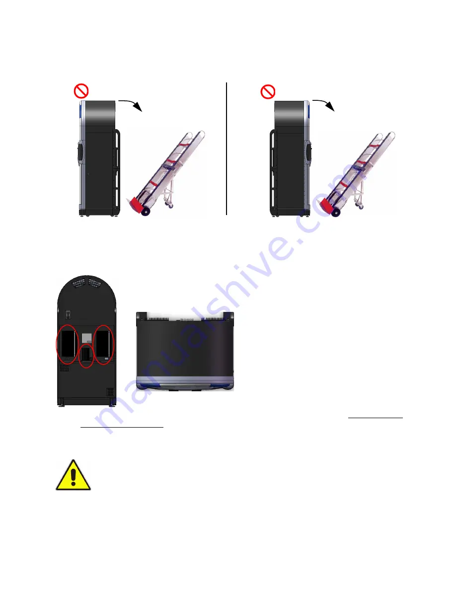
• By tilting the jukebox backwards onto a cart, you risk placing the weight of the jukebox on the 

heat sinks of the 2 amplifiers, which may cause them to dislodge from their mountings on the 
service tray and become vulnerable to subsequent damage

Incorrect

Incorrect

Risk of damage to
amplifiers and/or power

Risk of cosmetic

damage to front.

supply.

.

Do Not Rest Jukebox on its Front or Back

Never Place a Load on the Power Supply and Amplifier Heat Sinks.

To provide optimum cooling capability, the heat sinks of the Allegro MX-1’s power supply and 
two digital audio amplifiers are on the exterior of the cabinet (mounted on the service tray at the 
rear).

When transporting the Allegro on the bed of a pickup truck or the floor of a van, always slide the 
unit on its transport rails into the vehicle, and let the weight of the cabinet rest solely on the 
transport rails. Do not introduce any obstacles between the vehicle’s floor and the cabinet that 
may cause the cabinet to rest on the heat sinks of the amplifiers or power supply.

When transporting the Allegro MX-1:

1. Turn off the system power switches on the Allegro MX-1’s computer and internal power 

supply.


NEVER LAY THE CABINET ON ITS BACK AND TRANSPORT IT WITH A HAND CART 
BENEATH IT!

Overhead view

Summary of Contents for Allegro MX-1v

Page 1: ......

Page 2: ...this publication may be reproduced stored in any retrieval system or transmitted in any form or by any means electronic mechanical recording or otherwise without prior written consent of TouchTunes I...

Page 3: ...rview 5 Introducing Allegro MX 1 5 Components and Features 6 Sound 6 Touch screen Monitor 7 Cabinet 7 Door 7 Payment Means 7 Remote Controls 8 Lightshow 8 Poster Frame 8 System 8 Amplifier Overview 8...

Page 4: ...Closing the Allegro MX 1 Case 43 Activating the Allegro MX 1 Screen 44 5 Activating the Jukebox 45 Activation Procedure 45 Power on the Jukebox 45 Configure the Jukebox 46 Error Scenarios 54 Encounte...

Page 5: ...ons 81 Appendix B Parts Catalog 83 Assembly 83 Parts List 104 Appendix C Return Authorization RA Procedure 109 Return Authorization Numbers RAs 109 Warranty Repair and Replacements 109 Out of Warranty...

Page 6: ......

Page 7: ...urself with the installation procedure before installing your Allegro MX 1 Related Documentation This guide is designed to get you started quickly with installing and activating a jukebox in a locatio...

Page 8: ...a screenshot does Jukebox Location Lists jukeboxes by their current location Exclamation point within a triangle Identifies operating and maintenance information to know before use Caution Power off...

Page 9: ...ion and location that will not interfere with its proper ventilation Do not let objects or liquids enter the product as they may touch dangerous voltage points or short out parts that could result in...

Page 10: ...ng information may be required when contacting TouchTunes Support Jukebox ID or PlayPorTT ID Jukebox model e g Allegro MX 1 Allegro Ovation Maestro II The serial number of any component you believe to...

Page 11: ...onents Introducing Allegro MX 1 The Allegro MX 1 is TouchTunes new re designed and streamlined floor model jukebox Allegro MX 1 U S and Canadian Models U S Model Dual bill acceptor and card reader Can...

Page 12: ...ity and reliability The most robust and reliable payment means to date Improved longer range remote control receiver Integrated amplification providing sound for 3 independent audio zones Unparalleled...

Page 13: ...ensor controlled service light providing illumination of the cabinet s interior and service tray for increased visibility and ease of service Mesh protection at bottom to prevent the entry of insects...

Page 14: ...s of the bottom part of the door and two channels for the two lenses on the top Polycarbonate Translucent PC lightshow lens External standard DMX interface Poster Frame Easy access requiring no tools...

Page 15: ...lity equal to high quality linear amplifiers High dynamic range compatible with digital media Feature Specification Four channel amplifier Three channel amplifier Uncompromising sound quality 9 9 Dyna...

Page 16: ...anels as well as controls and indicators on its front panel Refer to the following figures to identify all components and connections on the JCB for your jukebox Layout of JCB Top Panel a USB ports fo...

Page 17: ...ostic LED y Power button for monitor and acceptors Note The power button y does not turn off the jukebox computer Accessing Components This section explains how to gain access to Allegro MX 1 s main c...

Page 18: ...upply Service tray The service tray is hinged at the bottom and travels outward on two slide rails fastened to the upper part of the tray To prevent access by unauthorized personnel the service tray m...

Page 19: ...gage the rails from the locking tabs by pressing them inward toward the center of the enclosure and then pulling back as far as they can travel 4 Gently push the service tray outward letting it slide...

Page 20: ...leted servicing To close and lock the service tray 1 Push the service tray inward until it is flush with the rear wall of the cabinet Push tray inward 1 Snap rails firmly over locking tabs 2 Closing a...

Page 21: ...through the provided cable channel opening Do not route cables through any other openings in the jukebox such as air vents Otherwise the jukebox may overheat and shut itself down To prepare for cable...

Page 22: ...t are pointed toward the service tray providing illumination to the interior When the door is closed the service lighting extinguishes Note A reflective strip for the optical sensors is mounted on the...

Page 23: ...g monitor adjustments Note The controls on your model may differ Sample monitor control legend Accessing the monitor To remove the monitor entirely for servicing or replacement 1 Unscrew and remove th...

Page 24: ...on of monitor mounting screws Transporting Allegro MX 1 The Allegro MX 1 is equipped with transport handles built in to the rear of the enclosure Use these handles when transporting theAllegro MX 1 an...

Page 25: ...nd side Using a Hand Cart Note If tilting the jukebox from its left hand side onto a cart ensure that the door is closed securely and locked otherwise it may flip open causing damage or personal injur...

Page 26: ...he Allegro MX 1 s power supply and two digital audio amplifiers are on the exterior of the cabinet mounted on the service tray at the rear When transporting the Allegro on the bed of a pickup truck or...

Page 27: ...close to the rear of the vehicle remove it from the hand cart and position it with its back facing the vehicle 6 With an assistant tilt the jukebox backward and lift it onto the vehicle Slide jukebox...

Page 28: ...22 Allegro MX 1 An Overview...

Page 29: ...X 1 jukebox Before you install the jukebox you must ensure that you have received all jukebox hardware components and that both hardware components and the items in parts kit are in good condition To...

Page 30: ...m software Download the TouchTunes music catalog Report the number of plays per song for music royalty calculations Report daily income for the jukebox The connection to the Internet is provided throu...

Page 31: ...must be installed and configured properly for Internet access before you can set up a broadband connection for the jukebox Note Dial up Internet connection is supported and is available as an option...

Page 32: ...26 Pre Installation...

Page 33: ...ll and level the Allegro MX 1 1 With the jukebox case closed try to move the Allegro MX 1 both slightly forward and backward then slightly sideways to see if the jukebox is resting on its wheels If th...

Page 34: ...ellers 3 Raise the levellers until the Allegro MX 1 is resting on all of its wheels 4 Optional Repeat step 1 to ensure you can move the jukebox in all directions 5 Move the Allegro MX 1 slowly from wh...

Page 35: ...ks for all TouchTunes Allegro MX 1 jukeboxes are keyed exactly alike You can replace the pre installed lock in any TouchTunes jukebox with another lock that is keyed differently Replacing the lock in...

Page 36: ...etween SATA and IDE hard drives Operators who are accustomed to the older hard drives may inadvertently fail to seat the connector firmly enough into the JCB s hard drive slot when installing the hard...

Page 37: ...Tunes jukeboxes may find that the thumb screw on the SATA enclosure requires significantly more rotations before the hard drive is properly seated Do not hesitate to screw the enclosure in firmly ther...

Page 38: ...cured properly when The thumb screw is completely compressed and covered by the cowl head of the thumbs screw i e the spring is not visible There is no gap between the edge of the hard drive tray and...

Page 39: ...you have hand tightened the thumb screw you must use a screwdriver to finish tightening the screw Connecting the Allegro MX 1 to the Broadband Network To connect the Allegro MX 1 to the broadband netw...

Page 40: ...lue 5 5 White Blue Green 6 6 Green White Brown 7 7 White Brown Brown 8 8 Brown 5 Connect either end of the cable to the broadband modem or router 6 Route the free end of the cable in to the jukebox th...

Page 41: ...when the jukebox is shipped 3 channel amplifier zone 1 The 3 channel amplifier provides two RJ45 input and output connectors to connect the amplifier to other audio equipment via standard category 5...

Page 42: ...and zone 3 audio requirements 4 channel amplifier zones 2 and 3 Unlike the 3 channel model the 4 channel amplifier does not support daisy chaining of components the RJ45 connectors for Zones A and B...

Page 43: ...approximately 1 4 of wire 2 Locate the supplied four slot Euroblock connector for the satellite speakers 3 Loosen the screws along the top of the connector using a flat head screwdriver if necessary O...

Page 44: ...ight channel satellites Left channel satellites Euroblock Euroblock From EQ box To bass box Connecting Satellite Speakers 5 Using a flat head screwdriver tighten the screws to secure the speaker cable...

Page 45: ...be wired in parallel in order to provide a 4 ohm load to the amplifier CAUTION Bose model 141 speakers will not function with either the 3 channel or 4 channel amplifier Do not attempt connection of t...

Page 46: ...ful attention to the following connection instructions Please refer to the figure on page 35 while performing the installation 1 Ensure that the power supply cord is disconnected from the power connec...

Page 47: ...onnect the Allegro MX 1 to the main AC power close the jukebox and then turn it on in order to activate it Components within the Allegro MX 1 such as the JCB and internal amplifier are connected to a...

Page 48: ...ess ports of the service tray to secure these cables before closing the Allegro MX 1 To tighten the wire strain relief sliders 1 Optional Pull in and hold a short length 1 2 inches of each cable runni...

Page 49: ...ng the Allegro MX 1 Case Once you have turned on the Allegro MX 1 close and lock its case To close the jukebox 1 Close the Allegro MX 1 case by lifting the door upward slightly gently swinging it shut...

Page 50: ...jukebox out of night mode and activate its screen before setting up the jukebox 1 Press the POWER button on the wired remote for the jukebox Power button Locating the POWER button Note Buttons may be...

Page 51: ...ox 1 Power on the JCB as described in Connecting Power to the Allegro MX 1 on page 41 2 Power on the jukebox as described in Activating the Allegro MX 1 Screen on page 44 WARNING During the following...

Page 52: ...ed the Calibration screen appears Note If there is a corruption in the jukebox s ID chip or other serious error the Calibration screen will not appear but rather an error will be indicated See Encount...

Page 53: ...alibration Screen The Settings screen appears Select Settings to Use In the Settings screen you select where to get the jukebox settings from Settings include mixer levels credit rules the remote ID a...

Page 54: ...he customer interface Languages Screen Make your language selection s and then press Apply to continue Settings 1 Touch one of the following Settings Screen Note For new Gen 3 jukeboxes the only avail...

Page 55: ...alled a new hard drive into the jukebox Download the settings from the TouchTunes server Touch to retrieve the settings from the TouchTunes server For example use this option on a jukebox where the so...

Page 56: ...specify the nightly time range during which the jukebox will communicate with the TouchTunes server Use the corresponding plus and minus buttons to specify the starting and ending times for communicat...

Page 57: ...area of the screen allowing you to specify connection parameters To choose a dynamic DHCP broadband connection 1 Select DHCP to obtain an IP address automatically from the ISP or the location s route...

Page 58: ...and then re enter the correct information Use the Clear key to erase the entire contents of the IP address field Use the Cancel key to cancel the operation and return to the Calling Window and Connect...

Page 59: ...status LED indicators Network Status LED Indicators Local Ethernet Indicates whether an ethernet cable is properly connected to the jukebox and the jukebox is receiving a signal from it Host Resolving...

Page 60: ...d will not be registered on the jukebox until data access is restored 3 Verify the information in the Activity messages Activity Status Screen If necessary do one of the following To scroll the Activi...

Page 61: ...stomer interface Encountering a Serious System Error Under serious conditions whether major system problems with hardware or software an error screen appears upon jukebox initialization indicating tha...

Page 62: ...56 Activating the Jukebox...

Page 63: ...e Operator Interface The Operator interface is composed of all the screens that you reach via the Operator menu To activate the Operator Interface 1 Locate the Setup button on the front panel of the J...

Page 64: ...58 Post installation The jukebox displays the Operator main menu Operator Main Menu The Operator main menu is the root menu from which you can access all the other screens of the operator interface...

Page 65: ...ebox Concrete and metal provide more of a barrier than wood or plaster The remote control can also be affected by interference from other RF based devices The remote control is powered by two 1 5V AAA...

Page 66: ...e new three digit code to use The new code must be in the range 000 to 255 3 The red indicator light will light up for three seconds to confirm your selection If you enter an invalid code the light wi...

Page 67: ...keys Used to program the remote and for future use MIC VOL Raises and lowers the volume of the microphone within the limits set on the Mixer Settings screen P1 Give promotional credit Press and relea...

Page 68: ...ber 100 A window prompting you for the Unit ID of the PlayPorTT displays on the jukebox s screen Note The PlayPorTT ID must always be entered as a two digit number for example for unit 2 you must ente...

Page 69: ...you must turn this option OFF If your Allegro MX 1 has dual bill acceptors you must ensure that this option is turned ON Testing the Payment Acceptors You verify that the bill acceptor coin acceptor...

Page 70: ...displays Money Options screen Testing the Bill and Coin Acceptors To test the bill acceptor 1 In the COIN BILL ACCEPTOR area press the TEST button The test screen appears Bill and Coin Acceptor Test...

Page 71: ...ce Long pulse do not change this setting To change the settings follow the directions on the side of the bill magazine 3 Make sure that the bill is properly stacked Instructions for removing the bill...

Page 72: ...a credit card into the card reader with the magnetic strip up and to the right and then remove your card If your installation is successful a message displays as illustrated in the figure below Credi...

Page 73: ...tools To change the front panel poster 1 Unlock and open the jukebox as described in Opening the Main Enclosure on page 11 2 Locate the locking tabs of the poster bay The locking tabs are flexible and...

Page 74: ...Brightness 100 However other factors such as a location s ambient lighting can affect the display s contrast ratio view angle and readability The values provided here are just a representation and no...

Page 75: ...he SET button 6 Press the MENU button to exit the OSD Ensure that the brightness of your display is set to 100 To adjust brightness 7 Press the MENU button once 8 Press the right arrow button once 9 P...

Page 76: ...rface To enable DSP EQ 1 From the main Operator interface select the Sound menu and then select Zone 1 Out Turn on JCB DSP EQ Turning on DSP EQ 2 In the JCB DSP EQ area select ON You can repeat this p...

Page 77: ...r the current time Requirements Cabling Use standard Cat 5 cable RCA connectors Two RCA connectors male are required to connect the cable to the DI box By convention a red connector is used for the ri...

Page 78: ...t the RCA connectors from one end of the audio cable to the left and right outputs on the external audio device 2 Connect the other end of the audio cable to the left and right input RCA jacks on the...

Page 79: ...a Microphone A microphone can be connected to the jukebox The jukebox will automatically mute the song that is currently playing when the talk button on the microphone is activated Requirements Microp...

Page 80: ...700166 001 and the 4 pin Euroblock connector part no 100000 001 supplied with your parts kit Refer to the following figure when performing this procedure Connecting a microphone 1 Prepare the microph...

Page 81: ...rmation 5 Using a flat head screwdriver tighten the screws of the slots for the microphone to secure the speaker cable to the connector 6 Attach the Euroblock connector to the connector labelled MIC I...

Page 82: ...the input gain for the microphone Mixer Input Screen Note The Mixer Input screen includes a Microphone Boost button which is independently controllable for the three audio zones The default value is O...

Page 83: ...e cabinet once the wired remote is removed Wired remote mounting panel before and after removal To relocate the wired remote 1 Disconnect the RJ11 flat cable from its connector on the wired remote 2 R...

Page 84: ...78 Post installation...

Page 85: ...showing all connections within Allegro MX 1 jukebox components as well as those between the jukebox and other external components such as audio amplifiers You can refer to this diagram while setting...

Page 86: ...w console Zone 3 Left Zone 3 Right Zone 2 Left Zone 2 Right Optional to daisy chained sound system External video For future expansion Card reader To USB port no 6 Bass box House audio input Microphon...

Page 87: ...witch controls computer To 3 channel amp To 4 channel amp Video cable Serial cable Power cable Bill acceptor 1 Bill acceptor 2 where installed Coin acceptor where installed Touch screen ID chip port P...

Page 88: ...82...

Page 89: ...rmation to help you locate and identify the parts of your Allegro MX 1 jukebox Assembly Use the following illustrations and the table on page 104 to identify the parts of your Allegro MX 1 Note Models...

Page 90: ...84 Assembly 1 of 20...

Page 91: ...Assembly 85 Assembly 2 of 20...

Page 92: ...86 Assembly 3 of 20 See Assembly 7 of 20 for detail...

Page 93: ...Assembly 87 Assembly 4 of 20...

Page 94: ...88 Assembly 5 of 20...

Page 95: ...Assembly 89 Assembly 6 of 20...

Page 96: ...90 Assembly 7 of 20...

Page 97: ...Assembly 91 Assembly 8 of 20 See Assembly 9 of 20 for detail...

Page 98: ...92 Assembly 9 of 20...

Page 99: ...Assembly 93 Assembly 10 of 20 See Assembly 9 of 20 for detail...

Page 100: ...94 Assembly 11 of 20...

Page 101: ...Assembly 95 Assembly 12 of 20...

Page 102: ...96 Assembly 13 of 20...

Page 103: ...Assembly 97 Assembly 14 of 20...

Page 104: ...98 Assembly 15 of 20...

Page 105: ...Assembly 99 Assembly 16 of 20...

Page 106: ...100 Assembly 17 of 20...

Page 107: ...Assembly 101 Assembly 18 of 20...

Page 108: ...102 Assembly 19 of 20...

Page 109: ...Assembly 103 Assembly 20 of 20...

Page 110: ...STER SHADE 1 3 7d 900071 011 POSTER NOT SHOWN 1 8 400459 001 DOOR LENS LEFT 1 3 9 400459 002 DOOR LENS RIGHT 1 3 10 300217 001 LED STRIP WHITE 4 3 11 18 11 400445 001 DOOR MOUNTING PLATE LONG 2 4 12 4...

Page 111: ...j 400557 001 SPRING CLIP 2 9 22 SERVICE TRAY MOUNTING HARDWARE 8 22a WASHER M10 NYLON 4 8 22b 400577 001 SPRING COMPRESSION 2 8 22c WASHER WIDE M4 2 8 22d SCR X PAN M4 2 8 22e WASHER M10 2 8 25 300377...

Page 112: ...STOP 1 13 41d LOCKWASHER M19 1 13 41e NUT M19 1 13 41f LOCKWASHER M7 1 13 41g NUT M7 1 13 42 400443 001 CAMLOCK 1 13 43 400435 001 CABINET VENT GRILL UPPER 2 14 44 400461 001 WIRED REMOTE SPACER 1 14...

Page 113: ...20 73 300048 120 POWER CORD 10 1 19 74 300163 072 VGA CABLE 72 1 17 18 75 300198 060 WIRED REMOTE CABLE 60 1 17 18 76 300142 TBD INTERNET CABLE LENGTH TBD 1 17 NOT INCLUDED 77 300142 016 RJ45 AUDIO CA...

Page 114: ...6 450 SUBWOOFER CABLE PARALLEL 1 18 95 300407 120 SATELITE CABLE PARALLEL NOT SHOWN 2 96 300408 300 SATELITE CABLE CONNECT NOT SHOWN 2 97 400516 001 LOCK LATCH SPRING 1 13 98 700181 001 HEX DRIVER TIP...

Page 115: ...oduct and quantity specified on the original RA request can be returned with the RA Number issued If returning additional products to TouchTunes Interactive Networks a new RA Number shall be required...

Page 116: ...ing Ifaproduct is out of warranty TouchTunesInteractiveNetworks shallevaluate it fora minimum charge per unit Additional parts and labor charges may apply Prior to proceeding with the repair of a prod...

Page 117: ...ing TouchTunes Interactive Networks recommends returning products by United Parcel Service Federal Express DHL or another reputable freight forwarder All TouchTunes Jukeboxes should be returned on a p...

Page 118: ...s were paid in advance by freight collect or other means notify the carrier immediately to initiate a claims inspection TouchTunes Interactive Networks Customer Service shall provide assistance as nec...

Page 119: ...uchTunes Interactive Networks Inc 400 Sainte Croix Avenue Suite 200 E Montreal Quebec Canada H4N 3L4 TouchTunes Interactive Networks Inc 3455 Salt Creek Lane Suite 100 Arlington Heights IL 60005 USA T...

Page 120: ......

Reviews: