background image

31

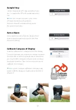
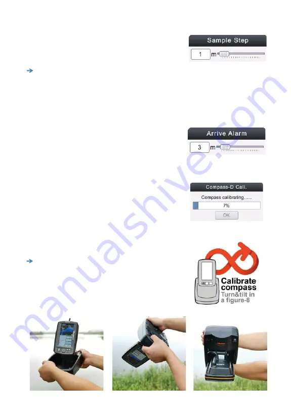
Sample Step

Set the distance for GPS data sampling. If you 
set 3, it means the GPS will sample data every 
3m.

     Note: 

the smaller the value is, the more

GPS data the device will generate.

However that will correspondingly cause
the system react slow.

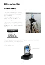
Calibrate Compass of Display

Used for calibration of compass built in the display

The device provide you an perfect compass function. 
However due to some unpected reason, sometime 
you may find the compass indicator does not show 
the proper direction. Then it is necessary for you to 
callibrate the compass.

Arrive Alarm

Arrive alarms sounds when the distance from
boat to target waypoint is equal or less than
the menu setting.


Note:

 when Compass calibration of display start, 

please hold the display on hand and turn & tilt it in 
a figure-8

Summary of Contents for TF740

Page 1: ......

Page 2: ...ce the risk of misusing or misinterpreting this unit you must read and under stand all aspects of this Installation and Operation Manual We also recommend that you practice all operations using the built in simulator before using this unit on the water Global Positioning System The Global Positioning System GPS is operated by the US Government which is solely responsible for its operation accuracy...

Page 3: ...e warnnings What s on the display Key Function Quickly Operation Start Using Set HOME position Save a waypoint Go to target waypoint Import KML Go back Menu Opertion Basic Sensivity Surface Clarify Fish ID Sens Background Color Adjust Color Style Advanced Mode Sonar Depth Range 2 5 6 7 7 10 12 13 15 17 17 18 19 20 22 22 22 23 24 25 26 26 26 26 26 27 27 27 27 28 28 ...

Page 4: ... Calibrate compass of display Calibrate compass of boat Autopilot Wirling Test Boat Type Channels Reverse Channel 1 Speed Channel 2 Speed Steering Sens System Simulator Backlight Key Tone Language Baud Rage Battery Alarm Boat Vtg Alarm Default Settings System Info Radio Bind 28 28 28 28 29 29 30 30 30 30 30 30 31 31 31 32 33 33 33 34 34 34 34 35 35 35 35 35 35 36 36 36 36 36 ...

Page 5: ...ration Quick Marker Waypoint Route Go back Set Home Pos Go to Home Stop Autopilot Clear Map Import KML Overlap Data Specifications Warranty Unit Care FAQ Frequenly Asked Questions 36 38 38 39 40 41 41 41 41 41 41 42 43 44 45 46 ...

Page 6: ...Lithium battery Charger Hardware Gain Adjustable Color Route to Indicate Depth 2D Map Advanced radio system FHSS DSSS What s the advantage of TF740 The TF740 was specially designed for bait boats It was combined with wireless Sonar High Position accuracy GPS and Autopilot The advanced sonar features show you actual bottom condition and ish The autopilot function can automatically guide the boat to...

Page 7: ...8 9 1 Display 2 SonarBox 740w 3 Autopilot CCU740 4 XGPS 740 5 Transducer 6 Rubber for transducer 7 SonarBox extending cable 8 Power cable 9 Servo cable 10 Antenna for boat 11 Antenna for display 12 Bracket of GPS receiver 13 Screws 4pcs 14 Valco 15 Antenna extending cable ...

Page 8: ...truction Transducer Knob Rubber Screw down the 2 screws to loose the battery support 1 take the knob and fake transducer down 3 screw tight the knob 5 installation was finished 6 hold the transducer with rubber through the boat 4 loose the knob of fixed fake transducer by hand 2 ...

Page 9: ...sducer groove on the boat bottom So you only need to simply match the transducer to the boat with a rubber Transducer Knob Rubber Transducer Mounting Instruction 1 Choose a proper position 2 Drille a hole 14mm on the selected position 3 Assemble the transducer and rubber 4 Hold the assembled transduer and rubber through the housing Then use the knob to screw tighten the transducer from the inner h...

Page 10: ...unting Instruction 1 Take off the transducer cover from the boat 2 Assemble the transducer and rubber 3 Hold the assembled transduer through the groove 4 Use the knob to screw tighten the transducer from the inner housing 5 The finished installation 1 2 3 4 5 keepthesharpendthesame directionwith head of boat Transducer Knob Rubber ...

Page 11: ...r Installation Transducer GPSreceiver Screws GPSbracket Take the GPS lid down from XBoat 1 Slid the GPS receiver to the GPS lid 3 Hold the assembled GPS receiver and lid going through the boat 4 Fix the GPS bracket on the GPS lid 2 ...

Page 12: ...icon of arrow on the GPS receiver should be oriented in the same direction with the heading direction of boat 4 After the installation please check the compass If you find the compass does not show proper direction please calibrate the compass by manual operation For the details please refer to page 31 Calibrate Compass of Boat 1 2 3 4 2 for general bait boats like Anatec Vegaboat etc Find a prope...

Page 13: ...wisher and the nut 5 Screw tighted the nut by an wrench 6 Finally screw the antenna on the boat Screwing the antenna to the boat will be ok for display for transmitter for display 2 for general bait boats like Anatec Vegaboat etc 1 for xboat730 Install antenna for transmitter In the package you can find 2 antennas one is for transmitter another is for display ded cable Antenna Installation Knob In...

Page 14: ...onnection After all the installatiion are finished please make the connection as following fiture Sonar Box Autopilot CCU Power DC12V Signalport toservo ESCofboat toremotereceiver toSonarBox 740W toantenna ...

Page 15: ...onnect the Autopilot CCU740 with your bait boat The system could control most 2 engineers or 1 engine with rudder boat with proper settings Xboat mode ESC of Right Motor ESC of Left Motor 2 Engines ESC of Right Motor ESC of Left Motor 1 Engine ESC Servo channel 3 channel 1 channel of right Motor channel of left Motor channel of ESC channel of servo Port A Transmitter connection function Port B ...

Page 16: ...ithium 12 6v battery pack as shown in the picture 2 Use a outer lithium battery Note 3S Lithium battery is optional users can buy it from local dealer DC15V 1A wall charger support optional The device work while battery charging support indicator LED of working 3S lithium battery pack 1 charging port 2 outer battery connection indicator LED of working Powering ...

Page 17: ...m Voltage 10 8v 14 8V 7 8V 10 6V 7 5V 12 8V 5 6 8 4V 8 4 12 6V 11 2V 16 8V Permission 12V lead acid 8AA NiMH 8AA Alkaline 2S Lithium 3S Lithium 4S Lithium Note overvoltage may burn the elements in the device From bellow shows the voltage range of the most popular batteries in the market ...

Page 18: ...ep it at least 1 2m above the ground 2 Please turn on the SonarBox and X Pilot CCU first then turn on the display Otherwise the display will indicate an error message as following 3 Please start using the device only when the Satellite Number reach more than 7 which means the GPS signal is strong enough Note the most satellite number TF740 can reach is 12 Radio module Fail Sonar module Fail GPS mo...

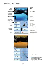
Page 19: ...o Home Time Speed of boat Voltage of display Depth range at bottom Fish symbol Structure Indicator of Boat heading direction Number of satellite Distance to Target Autopilot mode Remote mode Surface clutter Route of boat Note on the route different color means the depth changing of the water while the boat is running ...

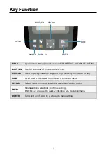
Page 20: ...us increase decrease a value of option POWER Turns unit on off Also be use to quit a menu setting PAGE ENTER ZOUT ZIN Used to zoom out GPS route on the screen Used to switch between main menus or some sub menus Finalizes menu selections confirm a setting ENTER key is also used to quickly enter into GPS Operation menu MENU ZOUT ZIN KEYPAD PAGE POWER PUSH GO ENTER Key Function ...

Page 21: ...20 Quickly enter into GPS operation Quickly enter into Waypoint Note pushing the key for 3s will start autopilot back to home Quickly Operation ...

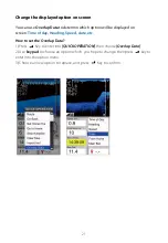
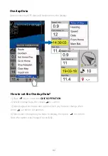
Page 22: ...keypad to choose an option which you hope to change then press key to enter into the option menu 3 Choose an new option to replace and press Key to confirm You can use Overlap Data to determin which option will be displayed on screen Time of day Heading Speed date etc Change the displayed option on screen ...

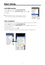
Page 23: ...oint 1 Press key to enter into QUICK OPERATION 2 Use keypad to choose Quick Marker then Press to enter into the waypoint detail info 3 Set the options and choose OK Now the waypoint was successfully created and saved in waypoint list Note After the device is powered on it will set the current location as default HOME Position Save a waypoint Set HOME position Start Using ...

Page 24: ...23 Go to target waypoint 1 Press key to enter into QUICK OPERATION 2 Use keypad to choose Waypoint then press to enter into waypoint list 3 Choose one target waypoint then press to select Go to target ...

Page 25: ...o QUICK OPERATION then choose Import kml 2 Import a kml file from the micro SD card 3 Move the cursor to a location on the map 4 Press key to confirm the location Then choose to save or go 5 After you choose Go the autopilot will start Note when you choose a location please guarantee there is no land obstacle betweem it and the boat land obstacle Import KML ...

Page 26: ...atically run to the second target 1 Press key to enter into QUICK OPERATION then use keypad to choose GO Back 2 Select the Target 1 and Target 2 from Waypoint list and Home Position and set delay time 3 The boat arrived the first target And after delaying the set time then run to the second target automatically ...

Page 27: ...rns being being displayed as fish which is helpful especially when you are intending to find smaller fish species or bait fish Surface Clarify Reduces surface clutter by decreasing the sensivity of the receiver near the surface Selecting a low setting will prevent weak sonar returns being displayed as fish which will be very helpful when you are seeking large species of fish Note If you hope to fi...

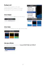
Page 28: ...for night time and white background for daytime is recommended Color Style Users can choose different color style for sonar image Color Adjust Adjust the contrast brightness of sonar image Advanced Mode To enable the advanced function of Sonar GPS SETTINGS AUTOPILOT ...

Page 29: ...makes the sonar more sensitive to echo returns allowing it to display weaker targets If the gain is set too high the image might be cluttered with background noise Note when set in shallow water mode the Gain option will be disable Overlap Data Used to select data shown on the top left conor of display Depth temperature Boat Bat Depth Offset Adjust the digital depth readout to indicate depth from ...

Page 30: ...29 Temp Offset Adjust the digital temperature readout to indicate temp from the waterline Shallow Alarm Sounds when the depth becomes equal to or less than the menu setting ...

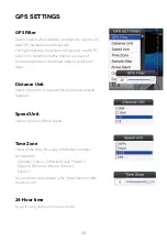
Page 31: ...nate data to avoid error data Speed Unit Selects the unit of boat speed 24 Hour time to set if using 24 hour time rule or not Distance Unit Selects the units of measure for all distance related readouts Time Zone Selects time zone for using in different countries For example Germany France Cetherland Italy Poland 1 Bulgaria Romania Ukraine Greece 2 Russia 3 For your time zone please refer http www...

Page 32: ...ration of compass built in the display The device provide you an perfect compass function However due to some unpected reason sometime you may find the compass indicator does not show the proper direction Then it is necessary for you to callibrate the compass Arrive Alarm Arrive alarms sounds when the distance from boat to target waypoint is equal or less than the menu setting Note when Compass ca...

Page 33: ...32 Calibrate Compass of Boat Used for compass calibration of the boat Note to calibrate compass of boat just put the boat on water and run it clockwise and anticlock wise ...

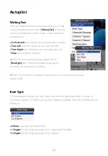
Page 34: ...esponding boat type NOTE before making the test please check Boat type and choose the relative boat option according to the type of your boat Go Forward test if the boat can go forward correctly Turn Left test if the boat can turn left correctly Turn Right test if the boat can turn right correctly Stop stop the boat running NOTE if you find the motor or rudder does not run at the correct way pleas...

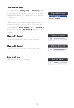
Page 35: ...cted For example if your boat are with 2 engines and you found the motor was running the counter direction when you push Go Forwarder in the Wiring Test then please enter into CH Reverse and select CH2 Reverse Steering Sens Set the sensitivity of boat steering Channel 1 Speed Limite the max speed of boat motor Channel 1 Channel 2 Speed Limite the max speed of boat motor Channel 2 ...

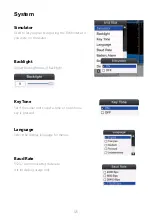
Page 36: ... if you were on the water Key Tone Set if the sonar unit sound a tone or not when a key is pressed Language Select the display language for menus Baud Rate RS232 communicating data rate It is for debug usage only Backlight Adjust the brightness of backlight System ...

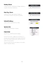
Page 37: ...r the TF740 each SonarBox has an Identity It only can be connected with one display And for all the TF740 Radio Binding process has been done in advance by our facotry However when you get a new display or SonarBox please re bind the device Boat Vtg Alarm Sounds when the input battery voltage of transmitter is equal to or less than the setting Default Settings Used to restore original factory sett...

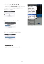
Page 38: ...irst select the Radio Bind from the operation menu and confirm it by pressing ENTER key A message will appear 2 Now power on the SonarBox 740 3 Press OK then Radio Bind was finished Update R Boxes Update the firmware of SonarBox 740 ...

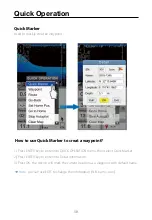
Page 39: ...t 1 Press ENTER key to enter into QUICK OPERATION menu then select Quick Marker 2 Press ENTER key to enter into Detail information 3 Press OK the device will mark the current location as a waypoint with default name Note you can use EDIT to change the information S N name icon Quick Operation ...

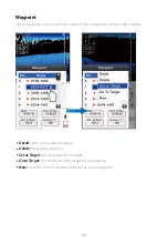
Page 40: ...These waypoints can be edit or delete Detail enter into waypoint details Delete delete the waypoint Set as Target set the waypoint as target Go to Target run the boat to the target by autopiloting New creat the currelnt location of boat as a new waypoint ...

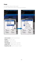
Page 41: ...ou can chose to save a route or load a route as target Save current save the current route Delete delete the route Rename rename the route Show Route show the route on screen Copy To SD copy the route to SD card Read From SD copy the route to SD card ...

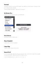
Page 42: ... Home Pos Set the current position of boat as HOME point Go to Home Guide the boat to HOME point Stop Autopilot Used to stop current navigation Clear Map Clear the route map on the screen Import kml You can import KML file from Google map to TF740 And run the boat with autopilot to a position on the map simply by moving the cursor For the detailed operation please refere to Page 24 ...

Page 43: ...p Data 1 Press key to enter into QUICK OPERATION 2 Select Overlap Data then press to confirm 3 Move keypad to choose one option which you hope to change then press an option list appears 4 Move select the option you hope to display then press to confirm Now the option was changed sucessfully ...

Page 44: ...Yes Direct sequence spread spectrum DSSS Yes Max Range 300m GPS Accuracy CEP 2 5m Compass at Boat Side Yes Compass at Dispaly Side Yes Waypoint Number 500 Routes to be Saved 10 Two propellers boat support Yes propeller Rudder boat support Yes Steering Sensitivity Adjustable Yes Wiring Test Mode Yes Push Go Key shortcut Yes Pick up waypoint form map Yes Google kml import to Define Lake Boundary Yes...

Page 45: ...s are covered by the warranty terms and condi tions for the remainder of the original product s warranty period six months or in accordance with local jurisdictions whichever is the greater The ownership of all parts removed from the product for the purposes of effecting warranty repairs transfers from the Owner back to Yachting electronic 3 Non Warranty Repairs Product s accepted for non warranty...

Page 46: ...n Debris in the keyboard contacts In case there is dirt or other debris covering the contacts inside the keypad press down on the button in question and wiggle it to try to restore its function Clean the connections Corrosion or oxidation could occur on the power cable connector pins This can prevent sufficient power from flowing to the unit Clean the connections to be sure Sometimes the substance...

Page 47: ...o the WIFI BLUETOOTH device or noisy R C controller may result in a very short RC communiction distance 1 The position accuracy of GPS depends on the satellites signal If the weather is cloudy or raining the satellites signal may become poor 2 If your boat with GPS receiver mounted is stationary the position coordinate may be drifting Then the error of GPS accuracy may reach 15 meters or even more...

Page 48: ...turning around at fast speed the compass display on screen may be delayed 4 If you find the compass completely does not show the proper direction please refer page 30 to calibrate the compass by manual operation 1 The mounted GPS receiver with compass built in should be far away from such substance magnets iron nickel etc 30cm distance is recommended 2 Please check the menu Boat Type and make sure...

Page 49: ...h compass built in should be far away from such substance magnets iron nickel etc 30cm distance is recommended 2 When wave is big boat can not run smoothly on the water the device always correct the route once the boat is far off track which my cause the boat going S shape route Please try decreasing the Steering Sens 1 For all sonar devices there are two blind regions even for the high frequency ...

Page 50: ...peed of boat with GPS receiver mounted on is less than 0 6m s the GPS data of boat heading direction will be always wrong And generally the boat is very slow when it is close to the desination So it is difficult for you to precisely operate the boat reaching to the desitination only with GPS function 2 With the compass you can observe the precise heading direction of boat even it is very slow fail...

Page 51: ......

Reviews: