Chapter2 Troubleshooting Procedures
Satellite U400/Satellite Pro U400/PORTEGE M800
Maintenance Manual 2-7
2.3 Power Supply Troubleshooting
The power supply controller controls many functions and components. To determine if the
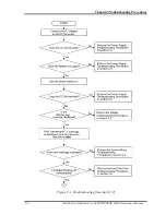
power supply is functioning properly, start with Procedure 1 and continue with the other
Procedures as instructed. The procedures described in this section are:
Procedure 1: Power Status Check
Procedure 2: Error Code Check
Procedure 3: Connection Check
Procedure 4: Charging Check
Procedure 5: Replacement Check
Procedure 1
Power Status Check
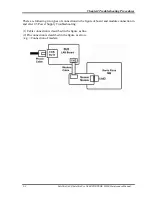
The following LED indicates the power supply status:
Battery LED
DC IN LED
The Power Supply control displays the power supply status with the Battery LED and the DC
IN LED as listed in the tables below.
Table 2-1 Battery icon
Battery icon
Power supply status
Lights orange
Battery is charged and the external DC is input. It has no
relation with ON/OFF of the system power.
Lights blue or white
Battery is fully charged and the external DC is input. It has
no relation with ON/OFF of the system power.
Blinks orange
(even intervals)
The battery level is low while the system power is ON.
Blinks orange once
(at being switched on)
The system is driven by only a battery and the battery level
is low.
Doesn’t light
Any condition other than those above.
Summary of Contents for Satellite Pro U400 Series
Page 110: ...Test Program for Field Satellite U400 and Satellite Pro U400 Tests and Diagnostics Manual 17 ...
Page 168: ...Replacement Procedures Satellite U400 Satellite Pro U400 PORTEGE M800 Maintenance Manual 4 iv ...
Page 276: ...Pin Assignment 36 Satellite U400 Satellite Pro U400 PORTEGE M800 Maintenance Manual ...
Page 302: ...Wiring Diagrams F 2 Satellite U400 Satellite Pro U400 PORTEGE M800 Maintenance Manual ...


