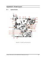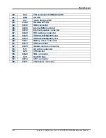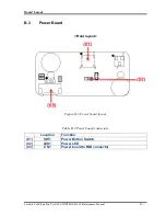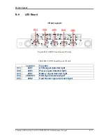
Board
Layout
B.4
Touch Pad Board
<Front layout>
Figure B-4-1 Touch Pad board layout (Front)
Table B-4-1 Touch Pad board connectors (Front)
Location
Function
(01)
CN4
Touch Pad board to Fingerprint board
connector(Upper)
(02)
SW4
Mouse Button Right key
(03)
SW2
Mouse Button Right key
(04)
CN5
Touch Pad board to Fingerprint board
connector(Lower)
(05)
SW3
Mouse Button Left key
(06)
SW1
Mouse Button Left key
B-8 Satellite U400/Satellite Pro U400/PORTEGE M800
Maintenance Manual
Summary of Contents for Satellite Pro U400 Series
Page 110: ...Test Program for Field Satellite U400 and Satellite Pro U400 Tests and Diagnostics Manual 17 ...
Page 168: ...Replacement Procedures Satellite U400 Satellite Pro U400 PORTEGE M800 Maintenance Manual 4 iv ...
Page 276: ...Pin Assignment 36 Satellite U400 Satellite Pro U400 PORTEGE M800 Maintenance Manual ...
Page 302: ...Wiring Diagrams F 2 Satellite U400 Satellite Pro U400 PORTEGE M800 Maintenance Manual ...


