Replacement Procedures
Satellite U400/Satellite Pro U400/PORTEGE M800
Maintenance Manual
4-iii
Figures
Figure 4-1 Remove the battery pack.................................................................................... 4-8
Figure 4-2 Install the battery pack ....................................................................................... 4-9
Figure 4-3 Remove Express card....................................................................................... 4-10
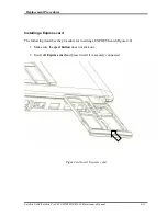
Figure 4-4 Insert Express card ........................................................................................... 4-11
Figure 4-5 Remove the HDD assembly ............................................................................. 4-13
Figure 4-6 Remove HDD................................................................................................... 4-14
Figure 4-7 Remove wireless LAN card ............................................................................. 4-16
Figure 4-8 Remove memory module ................................................................................. 4-19
Figure 4-9 Insert memory module ..................................................................................... 4-20
Figure 4-10 Remove screws for KBD cover/keyboard........................................................ 4-22
Figure 4-11 Remove the keyboard/KBD cover ................................................................... 4-23
Figure 4-12 Remove optical disk drive................................................................................ 4-25
Figure 4-13 Disassemble the side bracket ........................................................................... 4-26
Figure 4-14 Remove the screws from bottom side .............................................................. 4-28
Figure 4-15 Remove the screws from top side .................................................................... 4-29
Figure 4-16 Remove Wireless lan and LCD cable .............................................................. 4-29
Figure 4-17 Remove the hinge screw .................................................................................. 4-30
Figure 4-18 Remove the screws(back) ................................................................................ 4-32
Figure 4-19 Disconnect the touch pad flat cable/Fingerprint cable/Bluetooth Cable.......... 4-33
Figure 4-20 Remove the screws (front) and cover assy....................................................... 4-34
Figure 4-21 Remove the touch pad...................................................................................... 4-36
Figure 4-22 Remove the LAN board ................................................................................... 4-38
Figure 4-23 Disconnect the power cable ............................................................................. 4-39
Figure 4-24 Remove the system board ................................................................................ 4-40
Figure 4-25 Remove the CPU heat sink .............................................................................. 4-42
Figure 4-26 Remove the CPU.............................................................................................. 4-43
Figure 4-27 Applying silicon grease.................................................................................... 4-44
Figure 4-28 Remove the display mask................................................................................. 4-45
Figure 4-29 Remove the FL inverter ................................................................................... 4-46
Figure 4-30 Remove the LCD unit ...................................................................................... 4-47
Figure 4-31 Remove the LCD supports ............................................................................... 4-48
Summary of Contents for Satellite Pro U400 Series
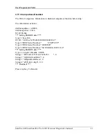
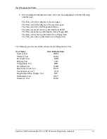
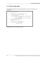
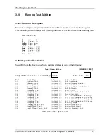
Page 110: ...Test Program for Field Satellite U400 and Satellite Pro U400 Tests and Diagnostics Manual 17 ...
Page 168: ...Replacement Procedures Satellite U400 Satellite Pro U400 PORTEGE M800 Maintenance Manual 4 iv ...
Page 276: ...Pin Assignment 36 Satellite U400 Satellite Pro U400 PORTEGE M800 Maintenance Manual ...
Page 302: ...Wiring Diagrams F 2 Satellite U400 Satellite Pro U400 PORTEGE M800 Maintenance Manual ...


