background image

User’s Manual

xx

A110 Series

Chapter 5, 

The Keyboard

, describes special keyboard functions including 

the keypad overlay and hotkeys.
Chapter 6, 

Power and Power-Up Modes

, gives details on the computer's 

power resources.
Chapter 7, 

HW Setup

, introduces you to the TOSHIBA Hardware Setup 

program.
Chapter 8, 

Optional Devices

, describes the optional hardware available. 

Chapter 9, 

Troubleshooting

, provides helpful information on how to perform 

some diagnostic tests, and suggests courses of action if the computer 

doesn't seem to be working properly.
Chapter 10, 

Disclaimers

, provides disclaimer information related to your 

computer.
The 

Appendixes

 provide technical information about your computer.

The Glossary defines general computer terminology and includes a list of 

acronyms used in the text.

Conventions

This manual uses the following formats to describe, identify, and highlight 

terms and operating procedures.

Abbreviations

On first appearance, and whenever necessary for clarity, abbreviations are 

enclosed in parentheses following their definition. For example: Read Only 

Memory (ROM). Acronyms are also defined in the Glossary.

Icons

Icons identify ports, dials, and other parts of your computer. The indicator 

panel also uses icons to identify the components it is providing information 

on.

Keys

The keyboard keys are used in the text to describe many computer 

operations. A distinctive typeface identifies the key top symbols as they 

appear on the keyboard. For example, 

Enter

 identifies the Enter key.

Key operation

Some operations require you to simultaneously use two or more keys. We 

identify such operations by the key top symbols separated by a plus sign 

(+). For example, 

Ctrl

 + 

C

 means you must hold down 

Ctrl

 and at the same 

time press 

C

. If three keys are used, hold down the first two and at the 

same time press the third.

Summary of Contents for Satellite A110 Series

Page 1: ...Choose freedom computers toshiba europe com Choose freedom computers toshiba europe com A110 Series GMR300613EN0 GMR300613EN0 User s Manual ...

Page 2: ...use the screen mode switching functions e g Wide mode Wide Zoom mode etc of this product to display enlarged images video at coffee shops or hotels for the purposes of profits or providing these to the public Disclaimer This manual has been validated and reviewed for accuracy The instructions and descriptions it contains are accurate for the A110 Series Portable Personal Computers at the time of t...

Page 3: ...your portable computer for an extended period of time with the base resting directly on your body With extended operation heat can potentially build up in the base Allowing sustained contact with the skin could cause discomfort or eventually a burn Do not attempt to service the computer yourself Always follow installation instructions closely Do not carry a battery in your pocket purse or other co...

Page 4: ... to turn on the computer When travelling with the hard drive removed from the computer wrap the drive in a non conducting material such as cloth or paper If you have the drive checked by hand be ready to install the drive in the computer Your can put the hard drive through an X ray security machine but never put it through a metal detector When travelling do not place the computer in overhead stor...

Page 5: ...Replace only with the same or equivalent type battery recommended by the manufacturer Dispose of used batteries according to the manufacturer s instructions To reduce the risk of fire use only No 26 AWG or larger telecommunication line cord TOSHIBA assumes no liability for any damage in such case When using telephone equipment in conjunction with your computer basic safety precautions should alway...

Page 6: ...ment and Telecommunications Terminal Equipment Directive 1999 5 EC in case of implemented telecommunication accessories and the Low Voltage Directive 73 23 EEC for the supplied power adapter CE Marking is the responsibility of TOSHIBA EUROPE GmbH Hammfelddamm 8 41460 Neuss Germany phone 49 0 2131 158 01 For a copy of the related CE Declaration of Conformity please refer to the following website ht...

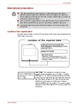
Page 7: ...he United States of America Department of Health Human Services Food and Drug Administration In other countries the drive is certified to comply with the requirement pursant to IEC 825 and EN60825 on class 1 laser product This computer is equipped with one of the optical drive in the following list according to the model Be sure to check the international precautions at the end of this section Man...

Page 8: ...vice location Use of controls adjustments or the performance of procedures other than those specified may result in hazardous radiation exposure To prevent direct exposure to the laser beam do not try to open the enclosure CAUTION This appliance contains a laser system and is classified as a CLASS 1 LASER PRODUCT To use this model properly read the instruction manual carefully and keep this manual...

Page 9: ...n bilve udsat for utilladellg kraftig stråling APPARATET BOR KUN ÅBNES AF FAGFOLK MED SÆRLIGT KENDSKAB TIL APPARATER MED LASERSTRÅLER Indvendigt i apparatet er anbragt den her gengivne advarselsmækning som advarer imod at foretage sådanne indgreb i apparatet at man kan komme til at udsætte sig for laserstråling OBS Apparaten innehåller laserkomponent som avger laserstråining överstigande gränsen f...

Page 10: ... for more details The hookflash timed break register recall function is subject to separate national type approvals It has not been tested for conformity to national type regulations and no guarantee of successful operation of that specific function on specific national networks can be given Important Notice Copyrighted works including but not limited to music video computer program databases are ...

Page 11: ...for a long time if you rest the computer on your lap for example your skin might suffer low heat injury If the computer has been used for a long time avoid direct contact with the metal plate supporting the I O ports It can become hot The surface of the AC adapter can become hot when in use This condition does not indicate a malfunction If you need to transport the AC adapter disconnect it and let...

Page 12: ...trial Environments e g environments where a mains voltage of 380V three phase is being used In the following environments the use of this product can be restricted Medical Environments This product is not certified as a medical product according to the Medical Product Directive 93 42 EEC but can be used in office areas where the use is not restricted Please disable the wireless LAN or Bluetooth ha...

Page 13: ... in radio frequency safety standards and recommendations TOSHIBA believes Wireless LAN is safe for use by consumers These standards and recommendations reflect the consensus of the scientific community and result from deliberations of panels and committees of scientists who continually review and interpret the extensive research literature In some situations or environments the use of Wireless LAN...

Page 14: ...ated to our company we do not take any responsibility Usage Restrictions Do not use the Wireless Products for controlling the following equipment Equipment directly linked with human life corresponding to the following Medical equipment such as life support systems equipment used in operations etc Exhaust systems for gases such as poisonous gas etc and exhaust systems for smoke Equipment that must...

Page 15: ...n aircraft or in places that generate or can generate radio interference Radio waves can potentially affect equipment such as that used on board aircraft causing an accident due to malfunction You should monitor possible radio interference or other issues that may arise with other equipment while the product is used If any effect is noted turn OFF the Wireless communication switch Otherwise radio ...

Page 16: ... 4 Back side 2 5 Underside 2 6 Front with the display open 2 7 Keyboard Indicators 2 9 Optical Disc drive 2 9 Chapter 3 Getting Started Setting up your work space 3 1 Connecting the AC adapter 3 4 Opening the display 3 5 Turning on the power 3 6 Starting up for the first time 3 6 Turning off the power 3 7 Restarting the computer 3 10 Restoring the pre installed software from the Product Recovery d...

Page 17: ... Setting up more than one display 4 23 Cleaning the computer 4 24 Moving the computer 4 24 Chapter 5 The Keyboard Typewriter keys 5 1 F1 F12 function keys 5 2 Soft keys Fn key combinations 5 2 Hotkeys 5 3 Windows special keys 5 4 Keypad overlay 5 4 Generating ASCII characters 5 6 Chapter 6 Power and Power Up Modes Power conditions 6 1 Power indicators 6 2 Battery types 6 3 Care and use of the batt...

Page 18: ...ty lock 8 15 Chapter 9 Troubleshooting Problem solving process 9 1 Hardware and system checklist 9 3 TOSHIBA support 9 16 Chapter 10 Disclaimers CPU 10 1 Memory Main System 10 2 Battery Life 10 2 HDD Drive Capacity 10 2 LCD 10 2 Wireless LAN 10 3 Non applicable Icons 10 3 Copy Protection 10 3 SRS 10 3 Images 10 3 LCD Brightness and Eye Strain 10 3 Appendix A Specifications Appendix B Display Modes...

Page 19: ...ontinue reading the preface to learn how this manual is organized then become acquainted with this manual by browsing through its pages Be sure to look over the Special features section of the A110 Features to learn about features that are unique to the computer Manual contents This manual has ten chapters four appendixes and a glossary Chapter 1 A110 Features is an overview of the computer s spec...

Page 20: ...ual uses the following formats to describe identify and highlight terms and operating procedures Abbreviations On first appearance and whenever necessary for clarity abbreviations are enclosed in parentheses following their definition For example Read Only Memory ROM Acronyms are also defined in the Glossary Icons Icons identify ports dials and other parts of your computer The indicator panel also...

Page 21: ...llowing software which is pre installed on your hard disc Microsoft Windows XP Home Edition DVD Video Player TOSHIBA Disc Creator TOSHIBA Direct Disc Writer TOSHIBA Power Saver TOSHIBA ConfigFree DISCCOPY A B When procedures require an action such as clicking an icon or entering text the icon s name or the text you are to type in is represented in the type face you see to the left ABC Names of win...

Page 22: ...sword Utility DVD RAM Driver Software InterVideo WinDVD Creator 2 Platinum Online Manual Product Recovery disc The availability of this software is dependent on the model you purchased Documentation Your computer s documentation A110 Series Personal Computer User s Manual A110 Quickstart Instruction Manual for Safety and Comfort Warranty information The system may not function properly if you use ...

Page 23: ...low power usage and high reliability This computer incorporates the following features and benefits Processor Disclaimer CPU For more information on the Disclaimer regarding CPU please refer to the Chapter 10 Disclaimers Basic features are described in a separate pamphlet Some of the features described in this manual may not function properly if you use an operating system that was not pre install...

Page 24: ...hics may vary depending on the graphics system applications utilized system memory size and other factors Slot Two DDRII SO DIMM up to 4GB with Intel 945GM Express Chipset up to 2GB with ATI RADEON Xpress 200M Chipset can be upgraded through the memory expansion slot You need to remove existing SO DIMM if SO DIMM is Maximum upgradable system memory size is depending on the system you purchased L2 ...

Page 25: ...pacity with system switched on Approximately 4 hours charge time to 100 battery capacity with system switched off Approximately 1 5 days discharging time in Standby Mode for the 8 cell battery 1 day for the 6 cell battery and 0 75 days for 4 cell battery Discharge time in shutdown mode is approximately 1 month The availability of this battery is dependent on the model you purchased RTC Battery The...

Page 26: ... on screen pointer 15 4 TFT LCD screen with one of the following resolutions WXGA 1280 horizontal 800 vertical pixels WXGA CSV 1280 horizontal 800 vertical pixels Fixed hard disk Depending on the model purchased one of the following drives will be installed 40 0 billion bytes 37 26GB 60 0 billion bytes 55 88GB 80 0 billion bytes 74 52GB 100 0 billion bytes 93 16GB 120 0 billion bytes 111 78GB 9 5m...

Page 27: ...M module that lets you record data to rewritable CD CD RWs as well as run either 12cm 4 72 or 8cm 3 15 CD DVDs without using an adapter It reads DVD ROMs at maximum 8x speed and CD ROMs at maximum 24x speed It writes CD Rs at up to 24x speed CD RWs at up to 24x speed This drive supports the following formats DVD ROM DVD Video CD R CD RW CD DA CD Text Photo CD single multi session CD ROM Mode1 Mode...

Page 28: ...aximum 5x speed This drive supports the same formats as the CD RW DVD ROM drive plus the following DVD ROM DVD Video DVD R DVD RW DVD R DVD RW DVD RAM DVD R double layer CD R CD RW CD DA CD Text DVD R dual layer Photo CD single multi session CD ROM Mode1 Mode2 CD ROMXA Mode2 Form1 Form2 Enhanced CD CD EXTRA Computers in this series can be configured with multiple types of optical disc drive For mo...

Page 29: ... A standard 3 5mm stereo jack is provided for the connection of external headphones or speakers Microphone jack A standard 3 5 mm mini microphone jack enables connection of monaural microphone input Modem An internal modem provides capability for data and fax communication It supports the V 90 or V 92 standards depending on the region and provides a modem jack for connection to a telephone line Th...

Page 30: ...ard disk drive when it is not accessed for a specified time period Power is restored when the hard disk is accessed You can specify the time period in the TOSHIBA Power Saver utility System Automatic Standby Hibernation This feature automatically places the system into either Standby Mode or Hibernation Mode when there is no input or hardware access for a specified time period You can specify the ...

Page 31: ...you turn off the power without exiting from your software The contents of main memory are saved to the hard disk When you turn on the power again you can continue working right where you left off Refer to the Turning off the power section in Chapter 3 Getting Started for details Standby In Standby Mode power to the system remains on but the processor and all other devices are effectively in sleep ...

Page 32: ...formation on the computer s configuration and allows some of the built in devices functionality to be tested You can start the TOSHIBA PC Diagnostic Tool as follows Start All Programs TOSHIBA Utilities PC Diagnostic Tool TOSHIBA Controls optional This utility allows you to configure the computer s audio video control buttons and setup the audio video playback applications Buttons Assign applicatio...

Page 33: ...are can be used on a model with a CD RW DVD ROM drive or a DVD Super Multi drive supporting R Double Layer TOSHIBA Direct Disc Writer TOSHIBA Direct Disc Writer is the packet writing software which provides the function to write files and or folders to DVD RW DVD RW or CD RW media via a drive letter like a floppy disk or other removable disk media TOSHIBA Touch and Launch TOSHIBA Touch and Launch ...

Page 34: ...ning on the feature To turn on the feature of the audio filter follow the steps below 1 Select Start point to All Programs TOSHIBA Utilities and Virtual Sound 2 TOSHIBA Virtual Sound setting window is displayed 3 Click On in the Basic Settings CD DVD Drive Acoustic Silencer This utility allows you to configure the read speed of CD drive You can either configure Normal Mode which operates the drive...

Page 35: ...rchased Battery Pack An additional battery pack can be purchased from your TOSHIBA dealer Use it as a spare to increase your computer operating time High capacity battery pack An additional battery pack can be purchased from your TOSHIBA dealer Use it as a spare to increase your computer operating time AC adapter If you use your computer at more than one site frequently it may be convenient to pur...

Page 36: ...e all possible configurations for an entire product series Your selected model may not have all the features and specifications corresponding to all of the icons or switches shown on the notebook chassis unless you have selected all those features 1 DC IN LED 2 Power LED 3 Battery LED 4 Hard Disk Drive LED 5 Multiple Digital Media Card Slot Access LED 6 Multiple Digital Media Card Slot 7 Wireless ...

Page 37: ...ard Slot Access LED The Multiple Digital Media Card Slot Access LED lights up when the Multiple Digital Media Card is accessed The availability of this function depends on the model you purchased Multiple Digital Media Card Slot The Multiple Digital Media Card Slot allows you to use media cards from digital still cameras and various forms of portable information equipment The availability of this ...

Page 38: ... configured with a full size optical disc drive module that lets you run either 12 cm 4 72 or 8 cm 3 15 discs without using an adapter See the Optical Disc drive section in this chapter for technical specifications on each drive and Chapter 4 Operating Basics for information on using the drive and caring for discs Optical Disc Drive LED This indicator lets you know when the Optical Disc Drive is b...

Page 39: ...rt Connect a 4 pin S video cable into this connector in order to output either an NTSC or PAL television signal i LINK IEEE1394a Port This port allows you to connect an external device such as a digital video camera for high speed data transfer The availability of this function depends on the model you purchased Universal Serial Bus USB Port The Universal Serial Bus USB 2 0 and 1 1 compatible port...

Page 40: ...ty cable attaches to this port in order to anchor your computer to a desk or other large object to deter theft LAN Jack This jack lets you connect to a LAN The adapter has built in support for Ethernet LAN 10 megabits per second 10BASE T and Fast Ethernet LAN 100 megabits per second 100BASE TX Two indicators built into the jack let you see the LAN status Universal Serial Bus USB Ports The Universa...

Page 41: ...n Chapter 8 Optional Devices Fan Vent The fan vent helps prevent the CPU from overheating To prevent possible overheating of the CPU never block the fan vent Battery Pack Latch With the Battery Pack Lock in its unlocked position you can slide this latch in order to remove the battery pack Battery Pack The battery pack powers the computer when the AC adapter is not connected For detailed informatio...

Page 42: ...n 8 Play Pause Button 9 Stop Button 10 Next Button 11 Previous Button 1 5 6 7 8 9 10 11 2 3 4 The availability of this feature is dependant on the model you purchased Display Screen The LCD displays high contrast text and graphics at a resolution up to 1280 800 pixels Refer to Appendix B Display Modes for further information When the computer operates from the AC adapter the display screen s image...

Page 43: ...click the TOSHIBA Controls icon CD DVD Button optional Pressing this button when the computer s power is off will run Windows Media Player Once Windows Media Player is launched the power indicator turns on the audio control buttons are enabled and pressing this button again will do nothing If you press this button while the computer is switched on or switched off into Standby Mode it will launch e...

Page 44: ...is selected in Windows Media Player selecting Next or Previous advances to a random selection Arrow Mode Numeric Mode Caps Lock Arrow Mode When the Arrow mode icon lights green you can use the keypad overlay light gray labelled keys as cursor keys Refer to the Keypad overlay section in Chapter 5 The Keyboard Numeric Mode You can use the keypad overlay light gray labelled keys for numeric input whe...

Page 45: ...recorded data cannot be erased or changed DVD RW DVD RW and DVD RAM discs can be recorded more than once CD RW DVD ROM drive The full size CD RW DVD ROM drive module lets you record data to rewritable CDs as well as run either 12 cm 4 72 or 8 cm 3 15 discs without using an adapter DVD Super Multi drive supporting R Double Layer The full size DVD Super Multi drive supporting R Double Layer module l...

Page 46: ... power source and the computer See Chapter 6 Power and Power Up Modes for details The AC adapter The read speed is slower at the centre of a disc and faster at the other edge DVD read 8 speed maximum DVD R write 8 speed maximum DVD RW write 4 speed maximum DVD R write 8 speed maximum DVD RW write 4 speed maximum DVD RAM write 5 speed maximum CD read 24 speed maximum CD R write 24 speed maximum CD ...

Page 47: ...r you and your computer A poor work environment or stressful work habits can result in discomfort or serious injury from repetitive strain to your hands wrists or other joints Proper ambient conditions should also be maintained for the computer s operation This section discusses the following topics General conditions Placement of the computer and peripheral devices Seating and posture Lighting Be...

Page 48: ...t place the computer near magnetic objects or bring magnetic objects close to the computer Be careful of objects such as stereo speakers that produce strong magnetic fields during operation Also be careful with metal objects such as bracelets which can be inadvertently magnetized Do not operate the computer in close proximity to a mobile phone Leave ample ventilation room for the fan Ensure that t...

Page 49: ...r chair so it supports the lower curve of your spine Sit straight so that your knees hips and elbows form approximately 90 degree angles when you work Do not slump forward or lean back too far Lighting Proper lighting can improve legibility of the display and reduce eye strain Position the computer so that sunlight or bright indoor lighting does not reflect off the screen Use tinted windows shades...

Page 50: ... if you suspect you might be suffering from a repetitive strain injury Please check every couple of months to ensure the fan inlets or exhaust vents see sections 2 4 and 2 6 are unobstructed Clean them if necessary A number of books are available on ergonomics and repetitive strain injury or repetitive stress syndrome For more information on these topics or for pointers on exercises for such stres...

Page 51: ...cord into a live wall outlet The Battery and DC IN indicators on the front of the computer should glow Opening the display The display panel can be rotated in a wide range of angles for optimal viewing 1 Push the display latch on the front of the computer Opening the display To disconnect AC adaptor you can follow the reversed procedure of Connecting AC adaptor Please hold the DC output plug porti...

Page 52: ... first time When you first turn on the power the computer s initial screen is the Windows XP Startup Screen Logo Follow the on screen directions for each screen During setup you can click the Back button to return to the previous screen Be sure to read the Windows Operating System End User License Agreement carefully Use reasonable care when opening and closing the display panel Opening it vigorou...

Page 53: ...ture provides the following benefits Can be configured so that data is automatically saved to the hard disc before the computer shuts down because of a low battery Make sure the built in hard disc drive and optical disc drive indicators are off before you switch the computer off If you turn off the power while a disc is being accessed you can lose data or damage the disc Do not turn the computer o...

Page 54: ...e appropriate settings according to the steps below 1 Open the Control Panel 2 Open Performance and Maintenance and open Power Options 3 Select the Hibernation tab 4 Select Enable Hibernate then click OK button 5 Open Toshiba Power Saver 6 Select Setup Action tab 7 Enable the desired Hibernation settings for When I press the power button and When I close the lid of my portable computer 8 Click the...

Page 55: ... rapidly than Hibernation Mode Saves power by shutting down the system when the computer receives no input or hardware access for the duration set by the System Standby feature You can use the panel power off feature If the computer is not used or accessed in any way including areas such as the receipt of an e mail for approximately 15 or 30 minutes when the AC adapter is connected it will automat...

Page 56: ...uire that you reset the system For example if You change certain computer settings An error occurs and the computer does not respond to your keyboard commands There are three ways to reset the computer system 1 Select Restart from the Shut Down dialogue box 2 If the computer is already on press Ctrl Alt Del 3 Press the power button to turn the computer off then press it a second to time in order t...

Page 57: ...se the up or down cursor key to select the CD ROM DVD drive in the display menu 4 Follow the on screen instructions Restoring TOSHIBA utilities and drivers If Windows is working properly individual drivers or applications can be separately restored The TOSHIBA Tools Utilities folder C TOOLSCD contains drivers and applications which are included with your computer system If your system drivers or a...

Page 58: ...chPad To use the TouchPad simply move your finger tip across it in the direction you want the on screen pointer to go TouchPad and control buttons The two buttons below the TouchPad are used like the buttons on a standard mouse Press the left button to select a menu item or to manipulate text or graphics designated by the pointer Press the right button to display a menu or other function depending...

Page 59: ...TouchPad twice Scroll Vertical Move your finger up or down the right edge of the TouchPad Horizontal Move your finger left or right along the bottom edge of the TouchPad The internal modem does not support the voice functions described in the help files All data and fax functions are supported In case of a lightning storm unplug the modem cable from the telephone jack Do not connect the modem to a...

Page 60: ...ion will also be displayed A check will appear next to the currently selected region and telephony location 4 Select a region from the region menu or a telephony location from the submenu When you click a region it becomes the modem s region selection and the New Location for telephony will be set automatically When you select a telephony location the corresponding region is automatically selected...

Page 61: ...and telephony location are incorrect Modem Selection If the computer cannot recognize the internal modem a dialogue box is displayed Select the COM port for your modem to use Dialing Properties Select this item to display the dialling properties Connecting To connect the modem cable follow the steps below 1 Plug one end of the modular cable into the modem jack 2 Plug the other end of the modular c...

Page 62: ...r move the computer while the cable is connected If you use a storage device such as an optical media drive or hard disc drive connected to a 16 bit PC Card you may find that the modem speed is slow or the communication session might be interrupted If you find that the modem speed is low or communication is interrupted when you are using the modem please set the CPU speed to Maximum within the TOS...

Page 63: ...e LAN cable To disconnect the LAN cable follow the steps below 1 Pinch the lever on the connector in the computer s LAN jack and pull out the connector 2 Disconnect the cable from the LAN hub in the same manner Check with your LAN administrator before disconnecting from the hub Wireless LAN The wireless LAN is compatible with other LAN systems that comply with the IEEE 802 11a b or 802 11g wireles...

Page 64: ...cation switch You can enable or disable the Wireless devices function with the on off switch No transmissions are sent or received when the switch is off Slide the switch forward to turn it on and backward to turn it off Wireless communication LED The LED indicates the status of the wireless communication functions Using optical disc drives The illustrations in this section might differ slightly f...

Page 65: ...ection for precautions on writing to CDs Loading optical disc media To load a disc follow the steps below 1 Turn on the power 2 a Press the eject button to open the drawer slightly Pressing the eject button b Pressing the eject button will not open the drawer when the computer s power is off If the power is off you can open the drawer by inserting a slender object about 15 mm such as a straightene...

Page 66: ...u feel it click into place The disc should lie below the top of the spindle flush with its base 6 Push the centre of the drawer to close it Press gently until it locks in place Be careful not to touch the lens or the area around it Doing so could cause the drive to malfunction If the disc is not seated properly when the drawer is closed it might be damaged Also the drawer might not open fully when...

Page 67: ...ntre of the drawer to close it Press gently until it locks into place Do not press the eject button while the computer is accessing the disc drive Wait for the optical disc indicator to go out before you open the drawer Also if the disc is spinning when you open it wait for it to stop before you remove it When the drawer pops open slightly wait a moment to make sure the disc has stopped spinning b...

Page 68: ...tions in the TOSHIBA Controls Properties CD DVD play control buttons optional Windows Media Player 10 Windows mode Icon AV Button DVD WinDVD5 CD WMP10 CD DVD Detect and activate media Detect and activate media Play Pause Play Pause Play Pause Stop Stop Stop Previous Previous chapter Previous tune Next Next chapter Next tune ...

Page 69: ...writing with this product Any change or loss of the recorded contents of CD R RW media that may be caused by writing or rewriting with this product or for any business profit loss or business interruption that may be caused by the change or loss of the recorded contents Damage that may be caused by using third party equipment or software Given the technological limitations of current optical disc ...

Page 70: ... any software that checks files automatically in the background Do not use hard disc utilities including those intended to enhance hard disc access speeds as they may cause unstable operation and damage data Write from the computer s hard disc drive to the CD Do not try to write from shared devices such as a LAN server or any other network device Writing with software other than TOSHIBA Disc Creat...

Page 71: ...ou write or rewrite to CD R RW or DVD R RW R RW RAM media read and follow all set up and operating instructions in this section If you fail to do so the DVD Super Multi drive supporting R Double Layer may not function properly and you may fail to write or rewrite lose data or incur other damage Disclaimer TOSHIBA does not bear responsibility for the following Damage to any CD R RW or DVD R RW R RW...

Page 72: ...ality of the disc and the way it is used CD R TAIYOYUDEN CO LTD MITSUBISHI KAGAKU MEDIA CO LTD RICOH Co Ltd Hitachi Maxell Ltd CD RW MITSUBISHI KAGAKU MEDIA CO LTD RICOH Co Ltd DVD R DVD Specifications for Recordable Disc for General Version 2 0 TAIYOYUDEN CO LTD Matsushita Electric Industrial Co Ltd DVD RW DVD Specifications for Re recordable Disc for Version 1 1 or Version 1 2 VICTOR COMPANY OF ...

Page 73: ...R RW standard it will be filled with dummy data if the written data is less than about 1 GB Even if you write only a small amount of data it might take time to fill in the dummy data Two types of DVD R R RW RW RAM discs are on the market data and video Use a video disc to store video data You can use video discs on a DVD recorder as well as on your computer s DVD ROM drive You cannot use data disc...

Page 74: ...rive Do not use shut down log off and standby hibernation while writing or rewriting Make sure writing or rewriting is completed before going into standby hibernation Writing is completed if you can open the drive tray Set the computer on a level surface and avoid places subject to vibration such as airplanes trains or cars Do not use an unstable surface such as a stand Keep mobile phones and othe...

Page 75: ... a DVD RAM use Explorer or other similar utility When you back up a DVD disc be sure the source drive supports recording to DVD R RW or DVD R RW discs If the source drive does not support recording to DVD R RW or DVD R RW discs it might not be backed up correctly When you back up a DVD R DVD RW DVD R or DVD RW be sure to use the same type of disc You cannot partially delete any data written to a C...

Page 76: ...t may be lost if writing fails due to an error on the disc When writing the Setup files for the program into a disc formatted by TOSHIBA Direct Disc Writer and starting Setup from this disc an error may occur In this case plase copy them to your hard disc and then run Setup When Using WinDVD Creator 2 Platinum You can record video back to your digital camcorder via i LINK IEEE1394a using WinDVD Cr...

Page 77: ...wing limitations when you write video DVD 1 Editing digital video Log in with Administrator rights to use WinDVD Creator Make sure that your computer is running on AC power when using WinDVD Creator Operate the computer at Full Power Do not use power saving features While you are editing DVD you can display previews However if another application is running the preview might not display properly W...

Page 78: ... or optical digital devices Please verify your disc after recording important data DVD R R RW discs cannot be written in VR format A maximum of about 2 hours of video data can be written in DVD Video format to DVD R R RW RW discs WinDVD Creator cannot export to DVD Audio VideoCD or miniDVD formats WinDVD Creator can write DVD RAM RW in VR format but the disc may only play on your computer When wri...

Page 79: ...iscs 6 If your discs become dusty or dirty wipe them with a clean dry cloth Wipe from the center out do not wipe in a circular direction around the disc If necessary use a cloth dampened in water or a neutral cleaner Do not use benzine thinner or similar cleaner Discs 1 Store your discs in the container they came in to protect them and keep them clean If a disc is dirty do not use cleaning fluid C...

Page 80: ...ows you to adjust more precisely the relative positioning of the two displays when they are configured as an extended desktop On the Display Properties window the two displays can be positioned horizontally vertically or in any diagonal configuration you wish as shown below TV Out Port If an external display will not be connected next time you use your computer you should cancel any extended deskt...

Page 81: ...taken when moving the computer will help ensure trouble free operation Make sure all disc activity has ended before moving the computer Check the Built in Hard disc Drive and optical disc drive indicators on the computer If a disc is in the disc drive remove it If a disc is in the optical disc drive remove it Also make sure the optical disc drive drawer is securely closed Turn off the power to the...

Page 82: ...he upper and lower case letters numbers punctuation marks and special symbols that appear on the screen There are some differences however between using a typewriter and using a computer keyboard Letters and numbers produced in computer text vary in width Spaces which are created by a space character may also vary depending on line justification and other factors The lowercase l el and the number ...

Page 83: ...to form soft keys Soft keys are key combinations that enable disable or configure specific features Emulation keys Your software may require you to use keys that the keyboard does not have Pressing the Fn key and one of the following keys simulates the enhanced keyboard s functions Press Fn F10 or Fn F11 to access the integrated keypad When activated the gray keys with white numbers become numeric...

Page 84: ...or simultaneous mode is set to WXGA 1280 800 If you connect an RGB Monitor that is not WXGA resolution change it in Display Properties Fn F6 Brightness Down Fn F7 Brightness Up Fn F8 Wireless Device Controls Pressing this hot key allows you to switch between active wireless devices if the wireless communication switch is switched on Fn F9 TouchPad On Off Fn F10 Cursor Keypad On Off This hot key en...

Page 85: ...d Turning on the overlays The numeric keypad overlay can be used for numeric data input or cursor and page control Arrow mode To turn on the Arrow mode press Fn F10 Arrow mode indicator lights Now try cursor and page control using the keys shown in the diagram below Press Fn F10 again to turn off the overlay Fn 1 Zoom Out To reduce the icon size on the desktop or the application window press the 1...

Page 86: ...ll keys will operate as if the overlay were off 2 Type upper case characters by holding down Fn Shift and pressing a character key 3 Release Fn to continue using the overlay Temporarily using overlay overlay off While using the normal keyboard you can temporarily use the keypad overlay without turning it on 1 Press and hold down Fn 2 Check the keyboard indicators Pressing Fn turns on the most rece...

Page 87: ...nerating ASCII characters Not all ASCII characters can be generated using normal keyboard operation But you can generate these characters using their ASCII codes With the overlay on 1 Hold down Alt 2 Using the overlay keys type the ASCII code 3 Release Alt and the ASCII character appears on the display screen With the overlay off 1 Hold Alt Fn 2 Using the overlay keys type the ASCII code 3 Release...

Page 88: ... are affected by the power conditions whether an AC adapter is connected whether a battery is installed and what the charge level is for the battery Power on Power off no operation AC adapter connected Battery fully charged Operates No charge LED Battery blue green DC IN blue green No charge LED Battery blue green DC IN blue green Battery partially charged Operates Charge LED Battery Amber DC IN b...

Page 89: ...igger point Operates Alarm sounds this function depends on how the computer is configured LED Battery flashes amber DC IN off Battery capacity exhausted Computer goes into Hibernation or shuts down depending on the TOSHIBA Power Saver setting No battery installed No operation LED Battery off DC IN off Power on Power off no operation The LED is dependent on the model you purchased Flashing Amber Th...

Page 90: ...urchase additional battery packs for extended use of the computer away from an AC power source The battery is a disposable item When its operation becomes short even when fully charged replace it with a new one Blue Green Indicates the AC adapter is connected and is correctly supplying power to the computer No light Indicates the AC adapter is not connected Blue Green Indicates power is being supp...

Page 91: ...IBA as replacements Do not remove the battery pack while the computer is in Standby Mode In this mode data is stored in memory so if the computer loses power it will be lost Battery type depending on the model you purchased 4 cell PA3451U 1BRS PA3451U 1BAS 6 cell PA3465U 1BRS PA3465U 1BAS 8 cell PA3457U 1BRS PA3457U 1BAS The availability of this battery is dependent on the model you purchased ERRO...

Page 92: ...te Provides important information Danger 1 Never try to dispose of the battery pack by burning or expose it to a heating device such as a microwave oven The battery pack could explode and cause bodily injury 2 Never try to disassemble repair or otherwise tamper with a battery pack The battery pack will overheat and ignite Leakage of caustic alkaline solution or other electrolytic substances will c...

Page 93: ...t rash If it contacts your clothes promptly remove them to prevent the fluid from contacting your skin or eyes 2 Immediately turn off the power disconnect the AC adapter and remove the battery if any of the following events are observed in the battery pack offensive or unusual odor excessive heat discoloration or deformation Never use the computer again until it has been checked by a TOSHIBA servi...

Page 94: ...ending battery life in this chapter for procedures If the computer is continuously operated on AC power for an extended period more than a week the battery might fail to retain a charge It might not function efficiently over the expected life of the battery pack and the Battery indicator might not indicate a low battery condition 3 After the battery pack is charged avoid leaving the AC adapter con...

Page 95: ...uter In such case follow the steps below 1 Fully discharge the battery by leaving it in the computer with the power on until the power automatically shuts off 2 Plug in the AC adapter 3 Charge the battery until the Battery indicator glows green or blue depending the model you purchased Repeat these steps two or three times until the battery recovers normal capacity Battery type Power on Power off ...

Page 96: ...ard to which the battery supplies power Enabling Standby Mode or Hibernation Mode conserves battery power if you are frequently turning the computer off and on Where you store your programs and data Closing the display when you are not using the keyboard saves power Operating time decreases at low temperatures The condition of the battery terminals Make sure the battery terminals stay clean by wip...

Page 97: ...o replace a discharged battery pack with a charged spare when you are operating your computer away from an AC power source This section explains how to remove and install the battery pack Removing the battery pack To replace a discharged battery pack follow the steps below 1 Save your work 2 Turn the computer s power off Make sure the Power indicator is off 3 Remove all cables connected to the com...

Page 98: ... Disconnect all cables connected to the computer 3 Hold the battery pack so that the label faces down and the connectors on the battery face the connectors on the computer 4 Gently slide the battery into the battery bay until the latch clicks into place 1 3 2 The battery pack is a lithium ion battery which can explode if not properly replaced used handled or disposed of Dispose of the battery as r...

Page 99: ...can delete a password you must first enter the current password correctly Owner String text box You can use this box to associate text with the password After you enter text click Apply or OK then each time the computer is switched on this text will be displayed along with the prompt for the password Supervisor password If you set a supervisor password some functions will be restricted when a user...

Page 100: ...e makes the computer to enter Hibernation when the display panel is closed and turns it back on when the display panel is opened System automatic Standby Hibernation This feature automatically turns off the system in Standby or Hibernation mode if the computer is not used for a set duration Refer to Special features in Chapter 1 A110 Features for an explanation of how to set the duration The passw...

Page 101: ...ng HW Setup To run HW Setup click Start click Control Panel click Printers and Other Hardware and select TOSHIBA HW Setup HW Setup Window The HW Setup window contains the following tabs General Password Display Boot Priority Keyboard LAN and USB There are also these three buttons Some models are not equipped with the CPU tab OK Accepts your changes and closes the HW Setup window Cancel Closes the ...

Page 102: ...on lets you choose from the following settings Default Return all HW Setup values to the factory settings About Display the HW Setup version Auto Selected Selects an external monitor if one is connected Otherwise it selects the internal LCD Default LCD Analog RGB Selects both the internal LCD and external monitor for simultaneous display This option is displayed only for Core Duo Solo processor ba...

Page 103: ...u want and press Enter Keyboard Wake up on Keyboard When this feature is enabled and the computer is in Standby mode you can turn on the computer by pressing any key It is effective only for the internal keyboard and only when the computer is in standby mode USB Legacy USB Support Use this option to enable or disable legacy USB support If your operating system does not support USB you can still us...

Page 104: ...les the Built in LAN Enabled Enables Wake up on LAN Disabled Disables Wake up on LAN Default The Wake up on LAN function consumes power even when the system is off Leave the AC adaptor connected while using this feature Do not install or remove an optional memory module while Wake up on LAN is enabled Enabled Enables Built in LAN function Default Disabled Disables Built in LAN function ...

Page 105: ...ation of the following types of devices which are available from your TOSHIBA dealer Cards Memory PC card SD IO Input Output SD Secure Digital miniSD MMC Multi Media Card MS Memory Stick MS Pro Memory Stick Pro xD xD Picture Card cards Memory modules Power devices Battery pack AC adapter Peripheral devices External monitor Television i LINK IEEE1394a Security lock ...

Page 106: ...d on the left side of the computer The computer s hot install feature lets you install PC Cards while the computer s power is on To install a PC Card follow the steps below 1 Insert the PC Card 2 Press gently to ensure a firm connection Installing a PC card After installing the card refer to the card s documentation and check the configuration in Windows to make sure it is appropriate for your car...

Page 107: ...e Safely Remove Hardware icon on the Task Bar 2 Click the PC Card you want to remove 3 Press the eject button of the PC Card to extend it 4 Press the extended eject button to pop the card out slightly 5 Grasp the PC Card and remove it Removing a PC card Eject button ...

Page 108: ...igital Assistants which use flash memory Card Type Capacities SD 8MB 16MB 32MB 64MB 128MB 256MB 512MB 1GB 2GB miniSD 8MB 16MB 32MB 64MB 128MB 256MB 512MB 1GB 2GB MMC 8MB 16MB 32MB 64MB 128MB 256MB 512MB 1GB MS 8MB 16MB 32MB 64MB 128MB 256MB MS Pro 256MB 512MB 1GB 2GB xD 16MB 32MB 64MB 128MB 256MB 512MB 1GB 2GB Keep foreign objects out of the memory card slot A pin or similar object can damage the ...

Page 109: ... the Stop button A confirmation dialog may appear depending on how the device is registered with the system if so confirm that you want to remove the device 3 Gently press the memory card inside the socket to eject it Be sure the memory card is oriented properly before you insert it If Windows fails to read the card remove it then re insert it The multiple digital media card slot only accepts one ...

Page 110: ...o containers of liquid 7 After using a memory card return it to its case 8 Do not touch the metal part or expose it to liquids or let it get dirty Make sure the memory card indicator is out before you remove the card or turn off the computer s power If you remove the card or turn off the power while the computer is accessing the card you may lose data or damage the card Do not remove the card whil...

Page 111: ...ibernation mode data will be lost Some memory modules can be physically installed but are not compatible with the computer In this case the computer will issue a warning A110 Series There will be a long beep 3 short beeps 3 more short beeps and then a long beep when you turn the power on In this case shut down the power and remove the incompatible memory module CAUTION If you want to upgrade syste...

Page 112: ... ensure a firm connection 7 Push the module down so it lies flat Latches on either side will click into place to secure the module Installing a module 8 Seat the cover and secure it with the screw 9 Replace the battery pack as described in Chapter 6 Power and Power Up Modes 10 Turn the power on and make sure the added memory is recognized Do not touch the connectors on the memory module or on the ...

Page 113: ...hes to the outside to release the module A spring will force one end of the module up 5 Grasp the module and pull it out Removing the memory module 6 Seat the cover and secure its screw 7 Replace the battery If you use the computer for a long time the memory modules will become hot In this case let the memory modules cool to room temperature before you replace them Do not try to remove a memory mo...

Page 114: ...itor port 3 Turn the monitor s power on 4 Turn the computer on When you turn on the power the computer automatically recognizes the monitor To change the display settings press Fn F5 If you disconnect the monitor before you turn the computer off be sure to press Fn F5 to switch to the internal display Refer to Chapter 5 The Keyboard for details on using hot keys to change the display setting Telev...

Page 115: ...User s Manual 8 11 Optional Devices For the ATI Graphics Controller 1 Click Start Control Panel Display 2 Click the Settings tab 3 Click the Advanced button and choose Displays ...

Page 116: ...open the TV Properties dialog box 5 Adjust the TV properties accordingly 6 Adjusting the TV settings For the Intel Graphics Controller 1 Click Start Control Panel Appearance and Themes 2 Choose Display to open the Display Properties dialog box 3 Click Setting tab ...

Page 117: ...User s Manual 8 13 Optional Devices 4 Click the Advanced button and choose Intel Graphics Media Accelerator Driver 5 Click the Graphic Properties button and choose TV ...

Page 118: ...a particular risk that some frames will be deleted in the case of digital video transfer Do not transfer data in areas where static electricity is easily generated or in areas subjected to electronic noise Data can be destroyed If you are transferring data through an IEEE1394a hub do not connect or disconnect other devices from the hub during data transfer There is a likelihood that data will be d...

Page 119: ...ff functions Do not connect or disconnect an i LINK device while it is using an application or when the computer is automatically shutting it down to save power Data might be destroyed Disconnecting 1 Click the Safely Remove Hardware icon on the Task Bar 2 Point to i LINK IEEE1394a device and click 3 Disconnect the cable from the computer then from the i LINK device Security lock A security lock e...

Page 120: ...oblem related information that can help solve the problem Observe what is happening Write down what the system is doing and what actions you performed immediately before the problem occurred If you have a printer attached print a copy of the screen using PrtSc Isolate the problem Using the tools available to you such as the troubleshooting tips in this chapter try to discover the specific actions ...

Page 121: ...blem recurs the log will help you identify the problem faster Analysing the problem Sometimes the system gives clues that can help you identify why it is malfunctioning Keep the following questions in mind Which part of the system is not operating properly keyboard disk drives hard disk drive printer display Each device produces different symptoms Is the operating system configuration set properly...

Page 122: ...umentation These documents usually include a problem solving section or a summary of error messages Next check any error messages in the operating system documentation Hardware If you cannot find a software problem check your hardware First run through the items in the preliminary checklist above If you still cannot correct the problem try to identify the source The next section provides checklist...

Page 123: ...d check all cable connections as well as PC Card and memory module connections If the test fails again contact your dealer Power When the computer is not plugged into an AC outlet the battery pack is the primary power source However your computer has a number of other power resources including an intelligent power supply and Real Time Clock battery These resources are interrelated and any one coul...

Page 124: ...Power Up Modes Problem Procedure AC adapter doesn t power the computer DC IN indicator does not glow green or blue depending the model you purchased Check the connections Make sure the cord is firmly connected to the computer and a power outlet Check the condition of the cord and terminals If the cord is frayed or damaged replace it If the terminals are soiled wipe them with cotton or a clean clot...

Page 125: ...ary wipe them with a soft dry cloth dipped in alcohol Connect the AC adapter and replace the battery Check the Battery indicator If it does not glow let the computer charge the battery for at least 20 minutes If the Battery indicator glows after 20 minutes let the battery continue to charge for at least another 20 minutes before turning on the computer If the indicator still does not glow the batt...

Page 126: ...ake sure instant security was not activated Try entering your password if you have one registered Or turn the power off and back on to clear instant security Problems above remain unresolved or other problems occur Refer to your software s documentation to determine if the software is causing the difficulty Contact your dealer if the problems continue Problem Procedure Computer does not boot from ...

Page 127: ...mentation If problems persist contact your dealer Problem Procedure Cannot access Wireless LAN Make sure the computer s wireless communication switch is set to on Use the Config Free program that comes pre installed in your computer to see LAN status If problems persist consult your LAN administrator Problem Procedure PC Card error occurs Re seat the PC Card to make sure it is firmly connected Mak...

Page 128: ...resolution on the monitor might go into panning mode when wide screen resolution is selected Refer to Appendix B Display Modes Problem Procedure Problem Procedure No sound is heard Adjust the volume control dial Check the software volume settings If appropriate make sure the headphone connection is secure Check Windows Device Manager and ensure the sound function is enabled and that settings for I...

Page 129: ...uctions on cleaning If problems persist contact your dealer Problem Procedure Problem Procedure USB device does not work Check for a firm cable connection between the USB ports on the computer and the USB device Make sure the USB device drivers are properly installed Refer to your Windows documentation for information on checking the drivers If problems persist contact your dealer Problem Procedur...

Page 130: ...ot enter Standby Hibernation if Windows Media Player is either playing a selection or finished playing a selection Close Windows Media Player before you select Standby Hibernation If problems persist contact your dealer Problem Procedure The computer hangs up and issues beep sounds A long beep three short beeps three short beeps and then a long beep Make sure the memory module installed in the exp...

Page 131: ...cation when connection with the carrier is not successful for a set time interval Try lengthening this time interval A CONNECT display is quickly replaced by NO CARRIER Check the error control setting in your communications application Character display becomes garbled during a communication In data transmission make sure the parity bit and stop bit settings correspond with those of the remote com...

Page 132: ... dirty If it is wipe it with a clean cloth dipped in water or a neutral cleaner See the Media Care section in Chapter 4 for details on cleaning Some discs run correctly but others do not The software or hardware configuration may be causing a problem Make sure the hardware configuration matches your software s needs Check the disc s documentation Check the type of disc you are using The drive supp...

Page 133: ...ect external devices or install remove internal cards during writing If problems persist contact your dealer Problem Procedure Problem Procedure You cannot access a disc in the drive Make sure the drive s drawer is securely closed Press gently until it clicks into place Open the drawer and make sure the disc is properly seated It should lie flat with the label facing up A foreign object in the dra...

Page 134: ... Optical Disc drive section in Chapter 2 The Grand Tour Cannot write correctly If you have trouble writing make sure you are observing the following precautions Use only media recommended by TOSHIBA Do not use the mouse or keyboard during writing Use only the software supplied with the computer for recording Do not run or start other software during writing Do not jar the computer during writing D...

Page 135: ...leshooting suggestions Call the software company s technical support for assistance Consult the dealer you purchased your computer and or software from They are your best sources for current information and support Where to write If you are still unable to solve the problem and suspect that it is hardware related write to TOSHIBA at the location listed in the accompanying warranty booklet or visit...

Page 136: ...r low speed network connections use of complex modelling software such as high end computer aided design applications use of several applications or functionalities simultaneously use of computer in areas with low air pressure high altitude 1 000 meters or 3 280 feet above sea level use of computer at temperatures outside the range of 5 C to 30 C 41 F to 86 F or 25 C 77 F at high altitude all temp...

Page 137: ...ement settings and features utilized as well as the natural performance variations produced by the design of individual components Published battery life numbers are achieved on select models and configurations tested by Toshiba at the time of publication Recharge time varies depending on usage Battery may not charge while computer is consuming full power After going through many charge and discha...

Page 138: ...r than the theoretical maximum speed Non applicable Icons Certain notebook chassis are designed to accommodate all possible configurations for an entire product series Therefore please be aware that your selected model may not have all the features and specifications corresponding to all of the icons or switches shown on the notebook chassis Copy Protection Copy protection technology included in c...

Page 139: ...User s Manual A 1 Appendix A Specifications This appendix summarizes the computer s technical specifications Dimensions 360mm W 263mm D 38 5mm H Max 263mm 38 5mm 360mm ...

Page 140: ...Altitude from sea level Operating 30 to 10 000 feet Non operating 30 to 40 000 feet Network control unit NCU Type of NCU AA Type of line Telephone line analog only Type of dialling Pulse Tone Control command AT commands EIA 578 commands Monitor function Computer s speaker Communication specifications Communication System Data Fax Full duplex Half duplex Communication Protocol Data ITU T Rec Former...

Page 141: ...1600 24000 26400 28800 31200 33600 bps Data reception only with V 90 V 92 28000 29333 30666 32000 33333 34666 36000 37333 38666 40000 41333 42666 44000 45333 46666 48000 49333 50666 52000 53333 54666 56000 bps Fax 2400 4800 7200 9600 12000 14400 bps Error correcting MNP class 4 and ITU T V 42 Data compression MNP class 5 and ITU T V 42bis ...

Page 142: ...or CRT Display Resolution Color Depth bit Refresh Rate Hz 800 600 16 bit 60 75 85 100 32 bit 60 75 85 100 1024 768 16 bit 60 75 85 100 32 bit 60 75 85 100 1280 800 16 bit 60 32 bit 60 1280 1024 16 bit 60 75 85 100 32 bit 60 75 85 100 1600 1200 16 bit 60 75 85 100 32 bit 60 75 85 100 1920 1440 16 bit 60 75 32 bit 60 75 2048 1536 16 bit 60 32 bit 60 ...

Page 143: ...r computer s LCD and on an external TV or CRT monitor Follow the steps below For the ATI Graphics Controller 1 Open the Control Panel and click Display 2 Select the Settings tab and click Advanced 3 Click the Displays tab 4 Select the external display device you wish to use It must be connected to the computer in order to be selected from the menu here ...

Page 144: ...rties box if any additional options are available for your particular device set them to your liking 6 Finally click the ATI Overlay tab to adjust the video overlay properties 7 Click Setting tab 8 Click the Graphic Properties button and choose TV ...

Page 145: ...the Intel Graphics Controller 1 Click Start Control Panel Appearance and Themes 2 Choose Display to open the Display Properties dialog box 3 Click Setting tab 4 Click the Advanced button and choose Intel Graphics Media Accelerator Driver ...

Page 146: ...User s Manual B 5 Display Modes 5 Click the Graphic Properties button and choose TV 6 Adjusting the TV settings ...

Page 147: ...owing specifications Certification agencies Length Minimum 2 meters Wire size Minimum 0 75 mm2 Current rating Minimum 2 5 amperes Voltage rating 125 or 250 VAC depending on country region s power standards U S and Canada UL listed and CSA certified No 18 AWG Type SVT or SPT 2 Australia AS Europe Austria OVE Italy IMQ Belgium CEBEC The Netherlands KEMA Denmark DEMKO Norway NEMKO Finland FIMKO Swede...

Page 148: ...on must be a 2 15P 250V or 1 15P 125V and three pin plug coniguration must be 6 15P 250V or 5 15P 125V as designated in the U S National Electrical code handbook and the Canadian Electrical Code Part II The following illustrations show the plug shapes for the U S A and Canada the United Kingdom Australia and Europe USA United Kingdom UL approved BS approved Australia AS approved Approved by the ap...

Page 149: ...on form or a copy of it below Attach a copy of your receipt showing where your computer was purchased Either fax or send the receipt and registration form to the address below Always take care of your computer and try to prevent it from being stolen You are the owner of a valuable technical device which may be highly attractive to thieves so please do not leave it unattended in a public place To f...

Page 150: ...e the Stolen Units Database option Your entries are used to track your computer at our service points TOSHIBA Theft Registration Send to TOSHIBA Europe GmbH Technical Service and Support Leibnizstr 2 93055 Regensburg Germany Fax number 49 0 941 7807 921 Owner s details Country stolen Machine type e g A110 Series Model number e g PSA50 YXT Serial number e g 12345678G Date stolen Year Month Day Last...

Page 151: ...nly Memory CD RW Compact Disc Read Write CMOS complementary metal oxide semiconductor CPU central processing unit CRT cathode ray tube DC direct current DDC display data channel DMA direct memory access DOS disk operating system DVD digital versatile disc ECP extended capabilities port FDD floppy disk drive HDD hard disk drive IDE integrated drive electronics I O input output IrDA Infrared Data As...

Page 152: ...II American Standard Code for Information Interchange ASCII code is a set of 256 binary codes that represent the most commonly used letters numbers and symbols B BIOS Basic Input Output System The firmware that controls data flow within the computer See also firmware bit Derived from binary digit the basic unit of information used by the computer It is either zero or one Eight bits is one byte See...

Page 153: ... mark or symbol used by the computer Also synonymous with byte chip A small semiconductor containing computer logic and circuitry for processing memory input output functions and controlling other chips CMOS Complementary Metal Oxide Semiconductor An electronic circuit fabricated on a silicon wafer that requires very little power Integrated circuits implemented in CMOS technology can be tightly pa...

Page 154: ...er s memory It also writes data from memory to the disk To accomplish these tasks the unit physically rotates the disk at high speed past a read write head display A CRT LCD or other image producing device used to view computer output DOS Disk Operating System See operating system driver A software program generally part of the operating system that controls a specific piece of hardware frequently...

Page 155: ...certain keys in combination with the extended function key Fn can be used to set system parameters such as speaker volume I i LINK IEEE1394a This port enables high speed data transfer directly from external devices such as digital video cameras I O devices Equipment used to communicate with the computer and transfer data to and from it I O Input output Refers to acceptance and transfer of data to ...

Page 156: ...tal LSI Large Scale Integration 1 A technology that allows the inclusion of up to 100 000 simple logic gates on a single chip 2 An integrated circuit that uses large scale integration M megabyte MB A unit of data storage equal to 1024 kilobytes See also kilobyte mode A method of operation for example the boot mode standby mode or the hibernation mode modem Derived from modulator demodulator a devi...

Page 157: ...ade on a display or printer Also called a pel plug and play A capability with Windows that enables the system to automatically recognize connections of external devices and make the necessary configurations in the computer port The electrical connection through which the computer sends and receives data to and from devices or other computers prompt A message the computer provides indicating it is ...

Page 158: ... to the computer for data input output TFT display A liquid crystal display LCD made from an array of liquid crystal cells using active matrix technology with thin film transistor TFT to drive each cell TouchPad A pointing device integrated into the TOSHIBA computer palm rest U Universal Serial Bus This serial interface lets you communicate with several devices connected in a chain to a single por...

Reviews: