– 96 –
No. Part name
Procedure
Remarks
j
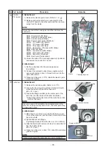
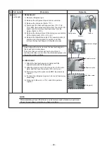
Drain pump
1. Detachment
1) Remove the drain pan. (Refer to
i
-1.)
2) Remove the drain pump connector (CN504: 2P, White)
connected to the control P.C. board and remove the
lead wires from the clamp.
3) Remove the fixing screws to remove the drain pump.
(Ø4 × 10, 3 pcs.)
4) Move the knob of the hose band which fixes the drain
hose a little from pump connecting part to the hose side,
and then remove the drain hose from the drain pump.
* Be careful that water may be out.
2. Attachment
1) Confirm the direction of the drain pump, and then fix it
with screws.
(Ø4 × 10, 3 pcs.)
2) Connect the drain hose to the drain pump.
* For the drain hose, insert up to the root of the
connecting part.
* Attach a band to the marked position of the hose,
and the knob of a hose band is attached to the deep
side of a set.
3) Pass the drain pump wiring through side plate and
clamp, and then connect the connector to the control
P.C. board.
4) Following to work in
i
-2, attach the drain pan, panel,
and electrical parts covers as original.
k
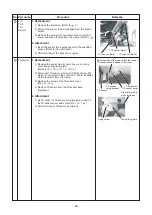
Float
switch
1. Detachment
1) Remove the drain pan. (Refer to
i
-1.)
2) Remove the float switch connector (CN34 3P, Red)
connected to the control P.C. board, and then take off
the lead wires from the clamp.
3) Remove the screws which fix the float switch.
(Ø4 × 8, 1 pc.)
4) Slide the float switch fixed bracket as direction shown
in the right figure, and then take off it from the claw.
2. Attachment
1) Insert the float switch fixing plate into the claw, and
tighten the fixing screw.
2) Pass the float switch lead wires through the side plate
and the clamp, and then connect the connector to the
control P.C. board.
3) Following to work in
i
-2, attach the covers of the
drain pan, panel, and electric parts box as original.
Dr
a
in p
u
mp
Ho
s
e
ba
nd
Dr
a
in ho
s
e
Fixing
s
crew
Lock rele
as
e direction
Fixing
s
crew
Cl
a
w
Flo
a
t
s
witch
fixing pl
a
te
Flo
a
t
s
witch


