


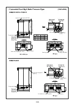

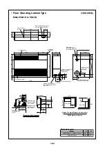
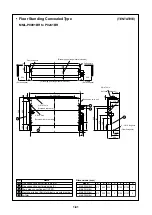


1-78
182.5
182.5
24
60
110
50
75
76
368
Ø
20
1055
210
77
450
480
380
20
400
75
75
75
75
75
75
75
75
690
45
13
22.5
160
344
50
50
16
83.5
120
70
18 – Ø6
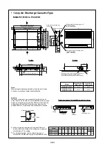
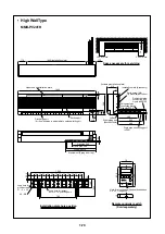
Installation plate hole position
Remote controller switch
(Sold separately)
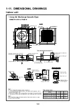
Space necessary for servicing
300 or more
300 or more
30 or more
Long hole for
wood screw
15 – 6 × 30
Upper end of
installation plate
Long hole for
anchor bolt
10-10 x 20 long hole
(Including installation plate)
Installation plate (Accessory)
Earth screw (M4) (In electric oarts box)
Drain pipe
connecting port
(VP20)
Discharge port
(Air flow direction is adjustable to up/down/left/right.)
Suction port
At shipment (Piping from left)
Liquid pipe 540
Drain pipe 560
Gas pipe 440
690 (Installation plate)
Refrigerant pipe connecting port
Liquid side L
Refrigerant pipe connecting port
Gas side K
Hole for mounting wall and embedded box
2–4.5 x 7 long hole
Left and Right piping port
(Knockout hole)
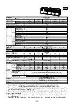
MMK-P0151H
MMK-P0181H
MODEL
6.4
9.5
12.7
15.9
Liquid side L
Gas side K
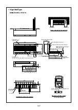
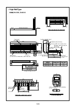
• High Wall Type
MMK-P0151H, P0181H


