


1-70
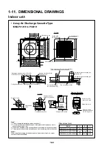
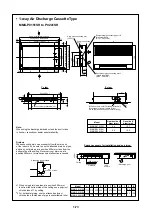
• 2-way Air Discharge Cassette Type
MMU-P0071WH to P0301WH
(TENTATIVE)
E
A
Air suction port (To 2 ways)
Z view
Air discharge port (Up to 2 ways)
Z
Dimensions (mm)
Model
A
B
C
D
E
F
G
H
I
L
O
P
Q
MMU-P0071WH to MMU-P0121WH
MMU-P0151WH
MMU-P0181WH to MMU-P0301WH
1000
1520
960
1480
880
1400
830
1350
650
620
550
480
265
295
—
—
—
Ø6.4
Ø9.5
12.7
19.0
19.0
35
398
8
156
Hanging bolt
4-M10 required at site
Ceiling panel
(Sold separately)
Knockout hole for discharge divided duct
(Provided also at opposite side)
Lower surface of ceiling
222
I
Ø
200
348
282
242
78
100
56
75 55
210
Q
Q
Refrigerant pipe
connecting port
(At liquid side O)
Wire
connecting
port
Water supply port
Drain pipe connecting port
(Inner dia. Ø32 polyvinyl
chloride pipe VP25 connected)
Refrigerant pipe connecting port
(At gas side P)
178
Ø
150
Knockout hole for fresh air
(At opposite side only)
95
60
35
30
Center of air condition
main unit
Center of panel
Unit external dimension D
Panel external dimension A
Ceiling open dimension B
Hanging bolt pitch C
20
70
P
anel e
xte
rn
al dimension E
Ceiling open dimension F
Unit e
xte
rn
al dimention G
Electric parts box
Hanging bolt pitch H
Note :
When using the discharge divided duct and the duct to take in fresh air,
consult your dealer about availability.
5mm
or more
1000mm or more
1000mm
or more
1000mm
or more
Obstacle
Lower surface
of ceiling
Rising up
160mm
or less
Rising up 508mm or less
100mm
or less
Indoor unit
Underneath of ceiling


