


1-1
1-2
SECTION 1 DESIGN MANUAL
1-1. OUTLINE OF MMS (Modular Multi System)
Compact design
The design of the modular TOSHIBA MMS outdoor unit allows for easy
unit maneuvering into any standard lift. Its compactness also allows
it to be easily installed in limited spaces.
Largest system capacity
TOSHIBA MMS modular multi system can be combined up to
46 HP (128kW) as one refrigerant system.
Energy saving
Compared with the conventional chiller fan coil system, a large energy
saving can be realized.
Advanced bus communication system
Wiring between indoor and outdoor unit is a simple 2 wire system.
Communication address is also automatically configured.
A default test mode operation is available.
Self diagnostics system
Comprehensive troubleshooting code allows for timely identification
of problems arising.
High lift design
Real pipe length of 100m (equivalent length 125m) and vertical lift
of 50m is made possible with TOSHIBA MMS system.
Vertical lift between indoor units of 30m is the highest in the industry.
This allows for greater flexibility in the location of the system.
Multiplied indoor units
Indoor units with different capacities and configurations can be
combined up to 135% of the outdoor unit capacity.
A maximum of 40 indoor units can be combined with the 40–46 HP
outdoor units.
Intelligent control
TOSHIBA MMS intelligent controls and modulating valves deliver the
required capacity, according to the load variation from 50% to 100%.
The intelligent controls and modulating valves limit or increase the
cooling capacity dynamically so humidity and temperature are kept
in the comfort zone.
Conforms to building control law
IAQ (Indoor Air Quality) is also achieved by combining various
accessories required by the Building Control Law.
Wide control applications
Artificial Intelligence Network system
• Central control and monitoring system available
• Weekly schedule operation through weekly timer
Integration with Building Management System (BMS)
is available.
Shortest route design by free branching
Header branching after header branching
Line branching after header branching
Line + Header branching
Header branching
Line branching
Outdoor unit
Outdoor unit
Outdoor unit
Outdoor unit
Outdoor unit
Indoor unit
Indoor
unit
Indoor unit
Indoor unit
Indoor unit
Branching joint
Branching joint
Branching joint
Branching
header
Header
Header
Header
Header
MMS Only
MMS Only
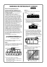
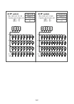
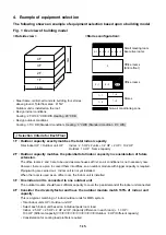
• Wiring diagnosis system
• Non-polarized control wiring
between outdoor and indoor units
Use the switches on the micro processor
P.C. board of the outdoor unit.
• Detects wiring to the indoor unit a4 which
should not be in system A.
• b4 is missing in system B.
8F
7F
2F
1F
Outdoor unit
Indoor unit
P Q
P Q
P Q
P Q
Indoor unit
Piping
Wiring
b1
b2
b3
b4
Outdoor
unit
A
system
Outdoor
unit
B
system
a1
a2
a3
a4
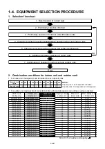
From 1st branching to the
farthest indoor unit : 50m
Outdoor
unit
Allowable pipe length :
100m actual length
(Equivalent to 125m)
Height diff
erence betw
een indoor
unit and outdoor unit :
50m
Height diff
erence betw
een indoor
unit and indoor unit :
30m
1st branching
section
Combination of line and header branching is highly flexible.
This follows for the shortest design route possible, thereby
saving on installation time and cost. Line/header branching
after header branching is only available with TOSHIBA MMS.


