


1-30
Basic function
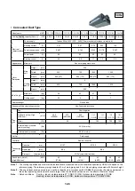
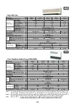
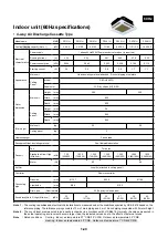
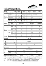
Model
System diagram
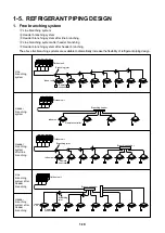
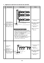
Function of central remote controller
• Air conditioner units can be set and run using an
indoor remote controller or central remote controller
based on “last-push priority” logic. Changed contents
overwrite the commands set previously.
(“Start/Stop”, “Cooling/Heating mode”, “Air Flow Set”,
“Temp. Set”, “Louver operation”)
• Start/Stop control of all indoor units in batch.
• Monitoring of operation for all indoor units.
(“Start / Stop”, ”Cooling/Heating mode“, “Air Flow Set”,
“Temp. Set”, “Louver operation”, “Filter Sign”)
• “Lock Function” for all indoor units.
• Central remote controller
TCB-SC641E
<Indoor remote controller>
• Main remote controller
RBC-AM1E
• Sub-remote controller
RBC-AS1E
• Remote controller with
timer
RBC-AT1E
Central management
controller for 64 groups
Group control of
Max. 64 groups x 16
units = 1,024 units
(one circuit can
have Max. 16 units)
• Central remote controller
TCB-SC641E
• Weekly timer
RBC-EXW1PE
<Indoor remote controller>
• Main remote controller
RBC-AM1E
or
• Sub-remote controller
RBC-AS1E
Central remote
controller
+
Weekly timer
Weekly operation
schedule
can be set by
connecting a weekly
timer to the central
remote controller
#1
#2
#3
#15
#16
#1
#2
#3
#15
#16
#1
#2
#3
#15
#16
Outdoor unit
Indoor remote controller
Indoor remote controller
Indoor remote controller
@1 line
@64 lines
Indoor unit
P,Q
X,Y
Single phase
220/230/240V
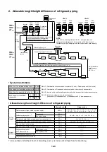
Grouping operation
• Indoor remote controller is required.
Power
supply
Central controller
@1
@2
@3
@15
@16
Outdoor unit
X,Y
P,Q
Indoor remote controller
Indoor unit
Possible to Max. l = 10m
Weekly timer
Central
remote controller
Power
supply
Single phase
220/230/240V
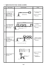
2-1
2-2
2. Application controls for central remote controller


