28
Display Explanation (cont.)
19: TIMER
21: CONTROL
Display
Description
Display
Description
Clock: Displays the current time
(AM or PM).
Lights while internal pump (P1) or
external pump (P2) is driven.
Displays days of the week (Sunday
to Saturday).
Lights during backup operation only by
the heater.
Lights when the NIGHT button is
pressed and goes out when the
button is pressed again.
Lights when the unit enters the data set
mode and goes out when the unit exits
the data set mode.
Lights when night time quiet
operation is set.
Lights when the unit enters the service
mode and goes out when the unit exits
the service mode.
Indicates scheduled operation 1
status (including setting time).
Lights when an error occurs and goes
out when the error is cleared.
Displays the scheduled operation
step when the scheduled operation
STEP1-5 program is set.
Lights for two seconds when settings are
completed.
Lights during time setting and
scheduled operation setting.
Lights for two seconds when settings
failed.
Remote Controller
– Schedule Timer
It is possible to set up timer control schedules on the ESTIA remote controller (when two remote controllers
are fitted to the ESTIA system the schedule timer is only available from the HEADER remote controller).
A maximum of eight control STEPS can be programmed / scheduled, into the ESTIA remote controller, for
each day of the week.
Using the schedule timer function (see page 42 for example):
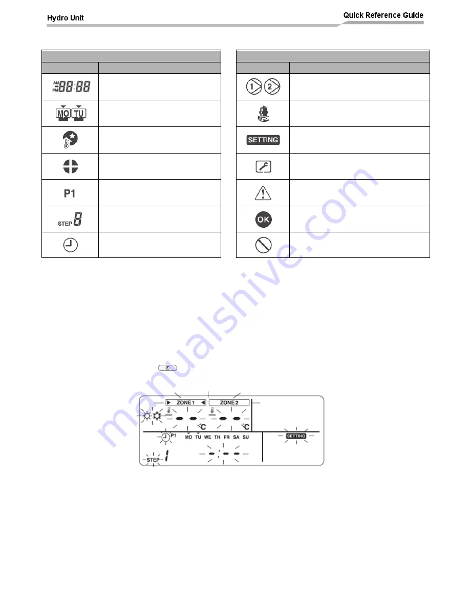
Accessing the schedule timer function
:
Press the SCHEDULE
button for 4 second or more to enter the schedule timer setting
mode. The remote controller will show the following display:
Specifying the day for the schedule timer:
Press the Day button to move the ▼symbol, displayed above the days of the week on the remote
controller, to the day when the scheduled timer id to take place. Each press of the DAY button
move
s the ▼symbol to the next displayed day. When the ▼symbol is above the required day, press
the SET button to confirm the day to be set
Specifying the control STEP number:
Press the STEP button to specify the control STEP to be set. The STEP selection increments by 1
STEP for each press of the STEP button from STEP 1 to STEP 8.
Steps “C” and “L” are also available by continuing to press the STEP button when the remote
controller display shows STEP 8.


