background image

Adjusting the Cutting Unit Rollers

The cutting unit rollers should be mounted in the lower
position when operating in height of cuts greater than 2-1/2
inches (64 mm) and in the higher position when operating in
height of cuts lower than 2-1/2 inches (64 mm).

1.

Remove the bolt and nut securing the gage wheel to
the cutting unit brackets (Figure 25).

Figure 25

1.

Gage wheel

2.

Align the roller and spacer with the top holes in the
brackets and secure them with the bolt and nut.
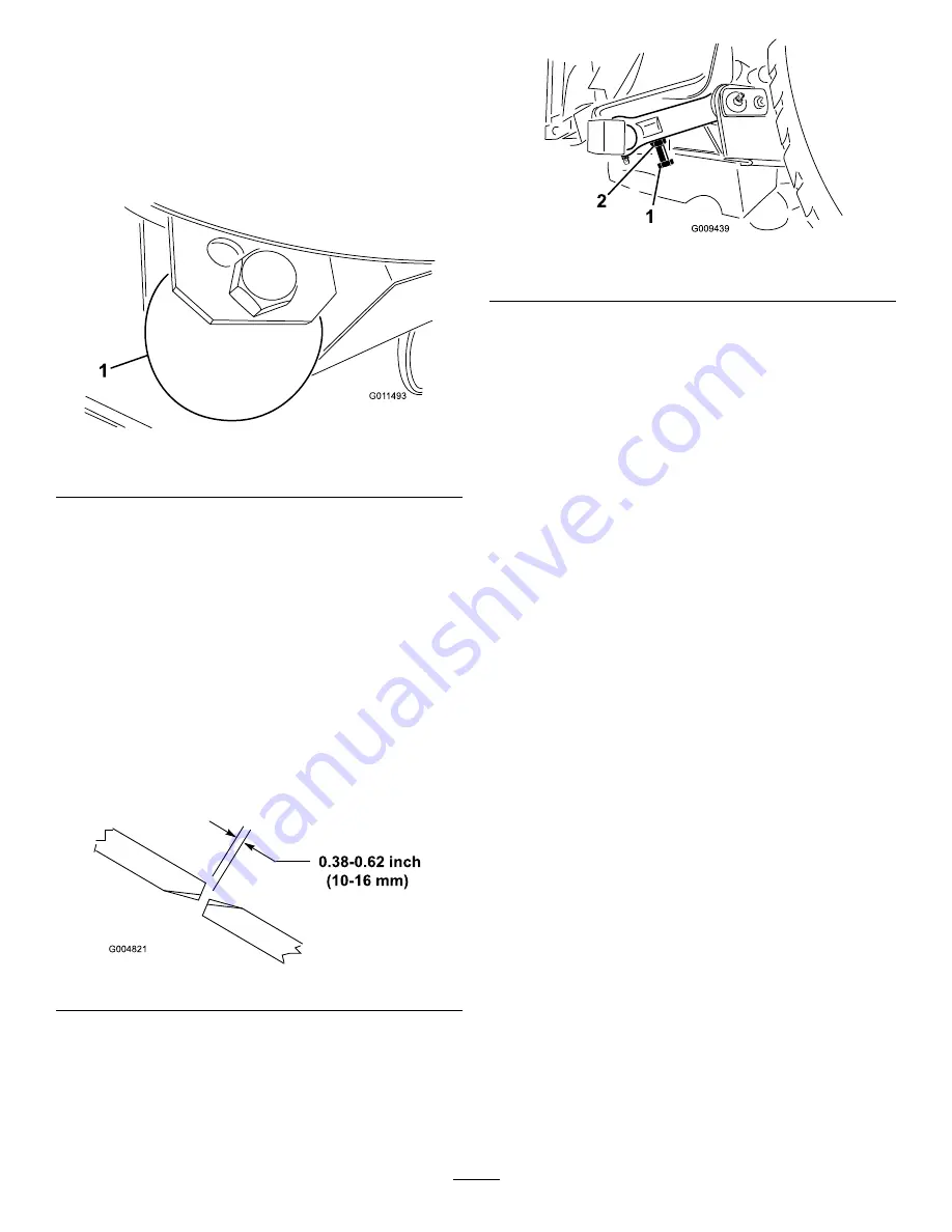
Adjusting the Blade

To ensure proper operation of the cutting unit, there must be
0.38-0.62 inch (10-16 mm) clearance between the tips of the
wing and center cutting unit blades (Figure 26).

1.

Raise cutting unit so blades are visible and block center
deck section so it cannot fall accidentally. Wing decks
must be horizontal to center cutting unit.

2.

Rotate a center and adjoining wing blade so there blade
tips are aligned. Measure distance between blade tips,
distance should be approximately 0.38-0.62 inch (10-16
mm) (Figure 26).

Figure 26

3.

To adjust distance, locate adjuster bolt on rear pivot
link of cutting unit (Figure 27). Loosen jam nut on
adjuster bolt. Loosen or tighten adjuster bolts until
0.38-0.62 inch (10-16 mm) clearance is attained, then
tighten jam nut.

4.

Repeat procedure on opposite side of cutting deck.

Figure 27

1.

Adjuster bolt

2.

Jam nut

Correcting Mismatch Between Cutting
Units

Due to differences in grass conditions and the counterbalance
setting of the traction unit, it is advised that a sample area of
grass be cut and appearance checked before formal cutting
is started.

1.

Set all cutting units to the desired height of cut; refer to
Adjusting the Height of Cut.

2.

Check and adjust front and rear tractor tire pressure to
25-30 psi (172-207 kPa).

3.

Check and adjust all castor tire pressures to 50 psi (345
kPa).

4.

Check charge and counterbalance pressures with
engine at high idle using test ports defined in Hydraulic
Systems Test Ports. Adjust counterbalance setting to be
230 psi (1585 kPa) higher than charge pressure reading.

5.

Check for bent blades; refer to Checking for a Bent
Blade.

6.

Cut grass in a test area to determine if all cutting units
are cutting at the same height.

7.

If cutting unit adjustments are still needed, find a flat
surface using a 6 foot (2 m) or longer straight edge.

8.

To ease measuring blade plane, raise the height of cut
to the highest position; refer to Adjusting the Height
of Cut.

9.

Lower cutting units onto the flat surface. Remove the
covers from the top of the cutting units.

10.

Loosen the flange nut, securing the idler pulley, to
release the belt tension on each cutting unit.

Center Cutting Unit Setup

Rotate blade on each spindle until the ends face forward and
backward. Measure from the floor to the front tip of the
cutting edge. Adjust 1/8 inch shims on front castor fork(s) to
match height of cut to decal (Figure 28); refer to Adjusting
the Cutting Unit Pitch.

25

Summary of Contents for 30447N

Page 1: ...3374 304 Rev A Groundsmaster 4100 D and 4110 D Rotary Mower Model No 30447N Serial No 313000001 and Up Model No 30449N Serial No 313000001 and Up Register at www Toro com Original Instructions EN 337...

Page 2: ...and on commercial grounds It is not designed for cutting brush mowing grass and other growth alongside highways or for agricultural uses Read this information carefully to learn how to operate and mai...

Page 3: ...hecking the Rear Wheel Toe In 42 Changing the Front Tires 42 Cooling System Maintenance 43 Servicing the Engine Cooling System 43 Brake Maintenance 44 Adjusting the Service Brakes 44 Belt Maintenance...

Page 4: ...wear substantial footwear long trousers hard hat safety glasses and hearing protection Long hair loose clothing or jewelry may get tangled in moving parts Do not operate the equipment when barefoot o...

Page 5: ...the blades running Keep hands and feet away from the cutting units Look behind and down before backing up to be sure of a clear path Slow down and use caution when making turns and crossing roads and...

Page 6: ...5 mm below the bottom of the filler neck Do not overfill Check the safety interlock switches daily for proper operation If a switch should fail replace the switch before operating the machine Check ca...

Page 7: ...ation of the machine use only genuine Toro replacement parts and accessories Replacement parts and accessories made by other manufacturers could be dangerous and such use could void the product warran...

Page 8: ...d in the operator s position 4 Warning wear hearing protection 5 Thrown object hazard keep bystanders a safe distance from the machine 6 Cutting hazard of hand or foot stay away from moving parts keep...

Page 9: ...1 Raise left deck 4 Cooling fan 2 Raise center deck 5 Reverse 3 Raise right deck 6 Automatic 119 0067 1 To lock the parking brake latch the pedals together apply the brake pedals and pull up on the kn...

Page 10: ...5 Turn signal 10A fuse 11 Powerpoint 7 5A fuse 6 Power seat 10A fuse 104 3579 1 Low height of cut adjustment 2 High height of cut adjustment 104 3599 1 Do not step here 2 Traction pedal 3 Traction fo...

Page 11: ...PTO push down on the PTO switch 6 To switch the transmission to high speed fully raise the attachments and switch the speed control to High Battery Symbols Some or all of these symbols are on your bat...

Page 12: ...rning do not touch the hot surface 2 Explosion hazard read the Operator s Manual 4 Warning read the Operator s Manual 120 6604 1 Thrown object hazard keep bystanders away from the machine 2 Cutting di...

Page 13: ...als 1 Review before operating machine Pre delivery Inspection Sheet 1 Note Determine the left and right sides of the machine from the normal operating position Greasing the Machine Before the machine...

Page 14: ...the pedals together to engage the parking brake Tilt Steering Lever Press the lever Figure 2 down to tilt the steering wheel to the desired position Then release the lever to lock the adjustment Park...

Page 15: ...Also the decks cannot be lowered from the transport position when the switch is in the high range If the switch is moved from LO to HI with the cutting decks down and or PTO on and or cruise control e...

Page 16: ...ld Wiper Switch Press front of switch to activate the wind shield wipers Figure 6 and rear of switch to turn off the wipers Air Conditioning Switch Press front of switch to activate the air conditioni...

Page 17: ...8 inch 147 cm Height with ROPS Height with cab 81 inch 206 cm 91 inch 231 cm Ground clearance 6 inch 15 cm Wheel tread to center of tire front 45 inch 114 cm rear 47 inch 119 cm Wheel base 55 1 2 inch...

Page 18: ...efore it has been started for the day If it has already been run allow the oil to drain back down to the sump for at least 10 minutes before checking If the oil level is at or below the add mark on th...

Page 19: ...his caution will damage the engine WARNING Fuel is harmful or fatal if swallowed Long term exposure to vapors can cause serious injury and illness Avoid prolonged breathing of vapors Keep face away fr...

Page 20: ...30 2 l of high quality hydraulic fluid Check the level of the hydraulic fluid before the engine is first started and daily thereafter The recommended replacement fluid is Toro Premium All Season Hydr...

Page 21: ...osition the wheel so that the check drain plug Figure 13 is at either the 3 or 9 o clock position Figure 13 1 Check drain plug 2 Add gear oil to the hole in the planetary if necessary to bring the oil...

Page 22: ...nce Do not under inflate Checking the Torque of the Wheel Nuts or Bolts Service Interval After the first 10 hours Every 200 hours WARNING Failure to maintain proper torque of the wheel nuts could resu...

Page 23: ...to the spindle shaft Install the tensioning cap to secure the assembly 5 Remove the hairpin cotter and clevis pin securing the height of cut chains to the rear of the cutting unit Figure 18 Figure 18...

Page 24: ...n rod to raise or lower pivot arm until holes are aligned with selected height of cut bracket holes in the cutting unit frame Figure 22 and Figure 23 6 Insert the clevis pins and install the hairpin c...

Page 25: ...h Between Cutting Units Due to differences in grass conditions and the counterbalance setting of the traction unit it is advised that a sample area of grass be cut and appearance checked before formal...

Page 26: ...ust the rear view mirror Figure 30 to attain the best view out the rear window Pull the lever rearward to tilt the mirror to reduce the brightness and glare of light Side View Mirrors While sitting in...

Page 27: ...ing the shop or the storage area Checking the Interlock Switches CAUTION If safety interlock switches are disconnected or damaged the machine could operate unexpectedly causing personal injury Do not...

Page 28: ...open and allow oil to bypass internally Because fluid is bypassed the machine can be slowly moved without damaging the transmission Note Resistance will be felt on the valve when it is moved to the op...

Page 29: ...is designed to drive objects into the ground where they lose energy quickly in grass areas However careless operation combined with terrain angle ricochets or improperly positioned safety guard can le...

Page 30: ...er than 1 4 inch 6 mm will result in less power required larger clippings and a poorer quality of cut A pitch less than 1 4 inch 6 mm will result in more power required smaller clippings and a better...

Page 31: ...connections Clean the underside of the mower housing and under the belt covers Every 100 hours Inspect the cooling system hoses and clamps Check the fan belt tension Every 150 hours Change the engine...

Page 32: ...bearings require no lubrication or short term maintenance This minimizes routine service required and reduces the potential of turf damage due to grease contamination These sealed bearing packages wil...

Page 33: ...hould only be lubricated annually 2 pumps Figure 37 Figure 38 Figure 39 Figure 40 Center Cutting Unit Note Deck may have to be raised to expose the grease fittings for the latch pivot and the lower li...

Page 34: ...42 Lower link pivot 4 Figure 43 Upper link pivot 4 Figure 43 Castor fork shaft bushings 2 Figure 44 Spindle shaft bearings 3 Figure 45 Idler arm pivot bushings 2 Figure 45 Figure 43 Figure 44 Figure...

Page 35: ...Figure 46 Lift arm ball joints 2 Figure 47 Figure 46 Figure 47 Wing Lift Assemblies Wing lift cylinder 4 Figure 48 Figure 48 Wing Cutting Units Castor fork shaft bushing 1 each Figure 49 Spindle shaf...

Page 36: ...aner cover 2 Air cleaner latch 2 Before removing the filter Figure 51 use low pressure air 40 psi clean and dry to help remove large accumulations of debris packed between outside of primary filter an...

Page 37: ...ls Do not fill the fuel tank completely full Add fuel to the fuel tank until the level is 1 inch 25 mm below the bottom of the filler neck This empty space in the tank allows the fuel to expand Never...

Page 38: ...curely 5 Repeat the procedure on the remaining nozzles Electrical System Maintenance Battery Care Battery type is group 24 Important Before welding on the machine disconnect the negative cable from th...

Page 39: ...arts of the machine WARNING Incorrect battery cable routing could damage the machine and cables causing sparks Sparks can cause the battery gasses to explode resulting in personal injury Always discon...

Page 40: ...uments 10A fuse 3 Engine start 20A fuse 9 Control module 2A fuse 4 Headlights 10A fuse 10 Control module 2A fuse 5 Turn signal 10A fuse 11 Powerpoint 7 5A fuse 6 Power Seat 10A fuse Note The cab fuses...

Page 41: ...bottom of the housing and allow the oil to drain 8 When all of the oil has drained install the plug in the housing 9 Add approximately 16 oz 0 5 l of high quality SAE 85W 140 gear lube to the planeta...

Page 42: ...easure the center to center distance at axle height at the front and rear of the steering tires The front measurement must be 1 4 inch 6 mm less than the rear measurement 2 To adjust loosen the clamps...

Page 43: ...the engine off and raise the hood Clean the engine area thoroughly of all debris 2 Remove the knobs Figure 67 securing the oil cooler to the frame Figure 67 1 Knobs 3 Pivot the oil cooler rearward Cle...

Page 44: ...ery 100 operating hours 1 Proper tension will allow 3 8 inch 10 mm deflection when a force of 10 lb is applied on the belt midway between the pulleys 2 If the deflection is not 3 8 inch 10 mm loosen t...

Page 45: ...t is ever removed from the mounting tab make sure it is reinstalled in the hole that aligns the stop bolt head with the idler arm 4 Remove the bolts securing the hydraulic motor to the cutting unit Fi...

Page 46: ...should contact the stop just before the pump is at full stroke to prevent any damage to the pump If it does not perform the following procedure 1 Park the machine on a level surface stop the engine an...

Page 47: ...ngine 5 Check the fluid level and add enough to raise level the level to the FULL mark on the dipstick Do not overfill Replacing the Hydraulic Filters Service Interval After the first 200 hours Every...

Page 48: ...e hydraulic fluid Use cardboard or paper to find hydraulic leaks Safely relieve all pressure in the hydraulic system before performing any work on the hydraulic system Seek immediate medical attention...

Page 49: ...rotates downward 2 Sit on the seat start the engine and lower the center cutting unit until it is slightly off of the floor 3 Secure the height of cut chains to the rear of the cutting unit 4 Pivot da...

Page 50: ...top of the castor spindle 3 Pull the castor spindle out of the mounting tube Allow the thrust washer and spacer s to remain on the bottom of the spindle 4 Insert a pin punch into the top or bottom of...

Page 51: ...ble the castor wheel push the bearing into the wheel hub When installing the bearings press on the outer race of the bearing 5 Slide the bearing spacer into the wheel hub Push the other bearing into t...

Page 52: ...cutting unit to ensure proper cutting Note After striking a foreign object torque all the spindle pulley nuts to 130 to 150 ft lb 176 to 203 N m Figure 86 1 Blade bolt 2 Anti scalp cup Inspecting and...

Page 53: ...blade with the anti scalp cup and blade bolt refer to Removing and Installing the Cutter Blade s Correcting Cutting Unit Mismatch If there is mismatch between the blades on a single cutting unit the...

Page 54: ...e more than three shims at any one hole location Use decreasing numbers of shims in adjacent holes if more than one shim is added to any one hole location 8 Adjust the idler pulley and install the bel...

Page 55: ...humb screws and grates from over both the in cab and rear cab air filters Figure 89 Figure 89 1 Thumb screw 3 Air filter 2 Grate 2 Clean the filters by blowing clean oil free compressed air through th...

Page 56: ...fo 112X skin over grease Toro Part No 505 47 or petroleum jelly to prevent corrosion D Slowly recharge the battery every 60 days for 24 hours to prevent lead sulfation of the battery Engine 1 Drain th...

Page 57: ...Schematics g014815 Electrical Schematic Rev D 57...

Page 58: ...g017775 Electrical Schematic Rev D 58...

Page 59: ...g017776 Electrical Schematic Rev D 59...

Page 60: ...g017779 Electrical Schematic GM 4000 4100 Rev D 60...

Page 61: ...g017780 Electrical Schematic GM 4010 Rev D 61...

Page 62: ...g017781 Electrical Schematic GM 4110 Rev D 62...

Page 63: ...g017782 Electrical Schematic GM 4010 Rev D 63...

Page 64: ...g017783 Electrical Schematic GM 4110 Rev D 64...

Page 65: ...g017784 Electrical Schematic GM 4110 Cab Rev D 65...

Page 66: ...g017785 Electrical Schematic GM 4110 Cab Rev D 66...

Page 67: ...Hydraulic Schematic Rev B 67...

Page 68: ...ed to damage to seats due to wear or abrasion worn painted surfaces scratched decals or windows etc Parts Parts scheduled for replacement as required maintenance are warranted for the period of time u...

Reviews: