2.
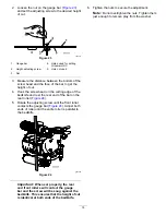
Raise the rear of the cutting unit and place a
block under the bedknife.
3.
Remove the 2 nuts securing each roller bracket
and spacer to each side-plate mounting flange.
4.
Lower the roller and screws from the side-plate
mounting flanges and spacers.
5.
Place the spacers onto the screws on the roller
brackets.
6.
Secure the roller bracket and spacers to the
underside of the side-plate mounting flanges
with the nuts previously removed.
7.
Verify that the bedknife-to-reel contact is correct.
Tip the mower to expose the front and rear
rollers and the bedknife.
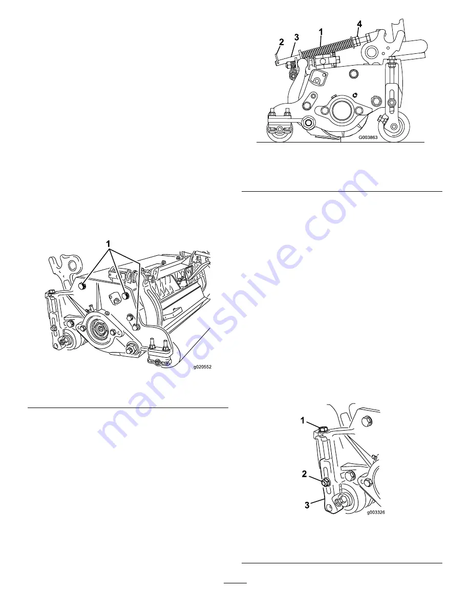
Note:
The position of the rear roller to the reel
is controlled by the machining tolerances of
the assembled components and paralleling is
not required. A limited amount of adjustment is
possible by setting the cutting unit on a surface
plate and loosening the side-plate mounting cap
screws (
).
g020552
Figure 20
1.
Side-plate mounting cap screws
8.
Adjust and tighten the cap screws and torque the
cap screws to 27 to 36 N∙m (240 to 320 in-lb).
Adjusting the Turf-Compensation
Settings
The turf-compensation spring transfers the weight
from the front to the rear roller. This helps to reduce
a wave pattern in the turf, also known as marcelling
or bobbing.
Important:
Make spring adjustments with the
cutting unit mounted to the traction unit, pointing
straight ahead and lowered to the shop floor.
1.
Make sure that the hairpin cotter is installed in
the rear hole in the spring rod (
g003863
Figure 21
1.
Turf-compensation spring
3.
Spring rod
2.
Hairpin cotter
4.
Hex nuts
2.
Tighten the hex nuts on the front end of the
spring rod until the compressed length of the
spring is 15.9 cm (6.25 inches); refer to
Note:
When operating on rough terrain
decrease the spring length by 12.7 mm (0.5
inch). Ground following will be slightly shorter.
Note:
You must reset the turf-compensation
setting if the HOC setting or the
aggressiveness-of-cut setting is changed.
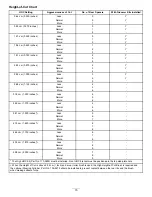
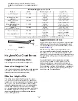
Adjusting the Height of Cut
(HOC)
Note:
For heights of cut greater than 2.54 cm (1.00
inch) install the High Height-of-Cut Kit.
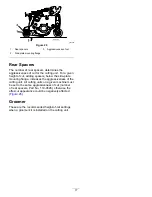
1.
Loosen the locknuts securing the height-of-cut
arms to the cutting-unit side plates (
).
g003326
Figure 22
1.
Adjusting screw
3.
Height-of-cut arm
2.
Locknut
13
Summary of Contents for 03698
Page 25: ...Notes ...


