
2.
Disconnect the lift chains from the cutting units,
if attached.
2
Mounting the Lift Brackets
and Chains
Parts needed for this procedure:
5/7
Lift chain
5/7
Chain bracket
5/7
U-bolt
10/14
Nut
5/7
Screw
5/7
Washer
5/7
Nut
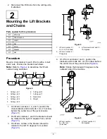
Procedure
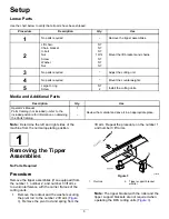
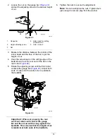
Mount a chain bracket to each lift arm with a U-bolt
and 2 nuts. Position the brackets as follows:
Note:
Refer to
to determine the lift arm
number being described.
g034112
Figure 4
1.
Cutting unit 1
6.
Cutting unit 6
2.
Cutting unit 2
7.
Cutting unit 7
3.
Cutting unit 3
8.
Reel motor
4.
Cutting unit 4
9.
Weight
5.
Cutting unit 5
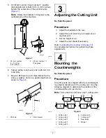
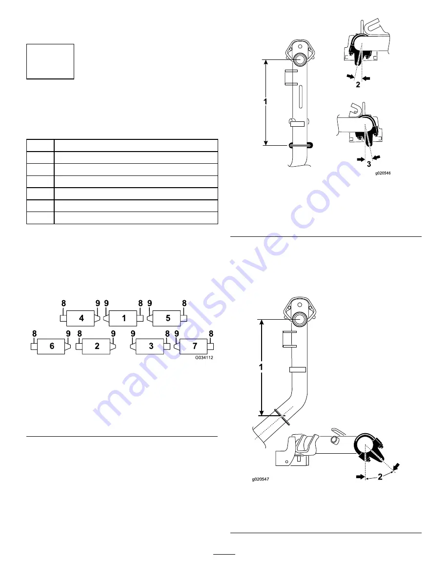
1.
On lift arm numbers 1, 4, and 5, position the
chain brackets and U-bolts 38.1 cm (15 inches)
behind the center line of the pivot knuckle
(
).
2.
On lift arm numbers 1 and 5 the brackets should
be rotated to the right 10 degrees from vertical
(
).
3.
On lift arm number 4 the bracket should be
rotated to the left 10 degrees from vertical
(
).
g020546
Figure 5
1.
Lift arm number 5 =
38.1 cm (15 inches)
3.
Lift arm numbers 1 and 5 =
10 degrees
2.
Lift arm number 4 =
10 degrees
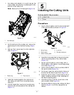
4.
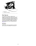
On lift arm numbers 2 and 3, position the
brackets and U-bolts 38.1 cm (15 inches) behind
the center line of the pivot knuckle (
Note:
Rotate the brackets 45 degrees to the
outboard side of the machine.
g020547
Figure 6
1.
Lift arm number
2 = 38.1 cm
(15 inches)
2.
Lift arm number 3 =
45 degrees
6
Summary of Contents for 03698
Page 25: ...Notes ...