Setup
Loose Parts
Use the chart below to verify that all parts have been shipped.
Procedure
Description
Qty.
Use
1
No parts required
–
Remove the tipper assemblies.
Lift chain
5/7
Chain bracket
5/7
U-bolt
5/7
Nut
10/14
Screw
5/7
Washer
5/7
2
Nut
5/7
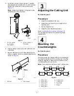
Mount the lift brackets and chains.
3
No parts required
–
Adjust the cutting unit
4
No parts required
–
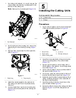
Mount the counterweights.
Large O-ring
5/7
5
Screw
2
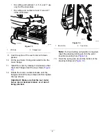
Install the cutting units.
Media and Additional Parts
Description
Qty.
Use
Operator's Manual
1
Parts Catalog (not included)—refer to the
included postcard for information on obtaining
the Parts Catalog
–
Review the material and save it in an appropriate place.
Note:
Determine the left and right sides of the
machine from the normal operating position.
1
Removing the Tipper
Assemblies
No Parts Required
Procedure
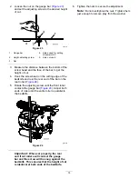
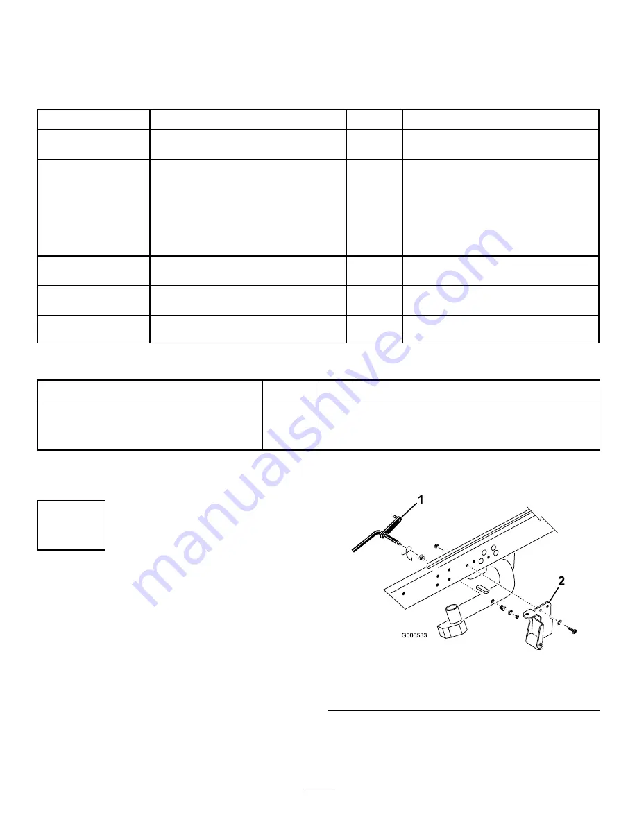
Remove the tipper assemblies (if so equipped) from
the number 1, number 2, and number 3 lift arms
to avoid interference with the carrier frames of the
cutting units.
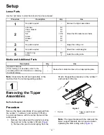
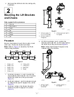
1.
Remove the locknut and the washer securing
the pivot rod to the number 2 lift arm (
). Remove the pivot rod and spring from the
lift arm. Repeat the procedure on the number 1
and number 3 lift arms.
g006533
Figure 3
1.
Pivot rod
2.
Tipper support bracket
w/roller
Note:
The tipper bracket with the roller and the
tipper support brackets are not required when
operating the DPA cutting units (
5
Summary of Contents for 03698
Page 25: ...Notes ...


