Topcon HiPER GD Operator'S Manual Download Page 74

Configuration

Topcon

HiPer GD and HiPer GGD Operator’s Manual

2-32

The Identification screen supplies current information 
concerning firmware version, serial number, frequency, and 
power of the radio modem.

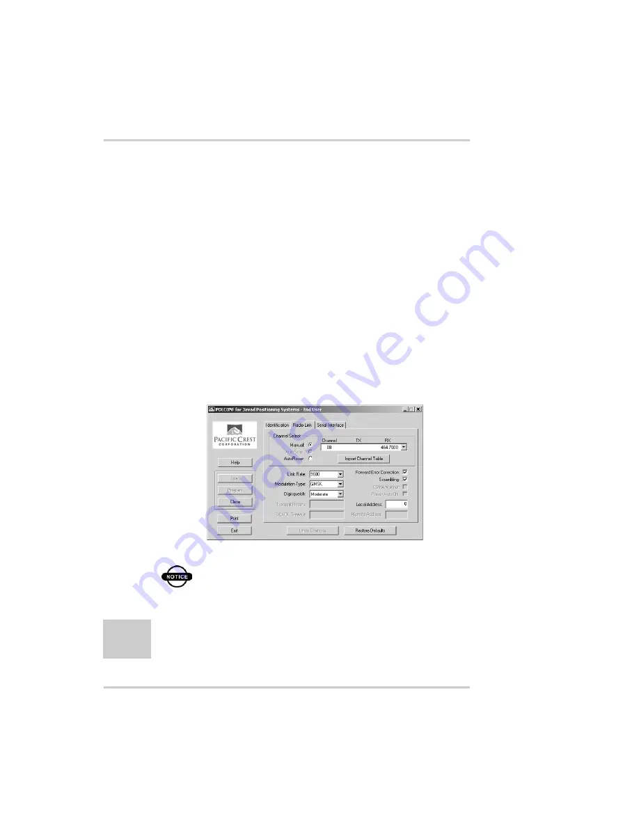
11. Click the Radio Link tab and set the following parameters 

(Figure 2-30):

• Manual – enable

• Channel TX RX – set channel and frequency as desired

• Link Rate – set to 9600 (requires a modulation type of 

GMSK)

• Digisquelch – set on High for Rover; Low for Base 

station

• Forward Error Correction – enable

• Scrambling – enable

• Local Address – leave at 0

Figure 2-30. PDL Radio Link Tab

NOTICE

The Base and internal receiver (Rover) PDL 
radios must be configured with the same 
Channels, Radio Link characteristics (except 
Digisquelch) and Serial Interface parameters.

Summary of Contents for HiPER GD

Page 1: ...PRECISION GPS HiPer GD HiPer GGD HiPer GD HiPer GGD Operator s Manual ...

Page 2: ......

Page 3: ...Manual Part Number 7010 0626 Rev A Copyright Topcon Positioning Systems Inc September 2003 All contents in this manual are copyrighted by Topcon All rights reserved The information contained herein may not be used accessed copied stored displayed sold modified published or distributed or otherwise reproduced without express written consent from Topcon ...

Page 4: ...ECO 2101 ...

Page 5: ... of Operation 1 3 GPS Overview 1 3 Calculating Positions 1 4 GPS Positioning 1 5 Conclusion 1 6 Receiver Overview 1 6 Standard Package Contents 1 8 Cables 1 8 Software 1 9 Literature 1 10 Getting Acquainted 1 10 Internal Components 1 11 GPS Antenna 1 11 Radio Modem 1 11 Power Board 1 13 GPS Receiver Board 1 14 Battery 1 15 External Components 1 15 Radome 1 15 Bottom Panel 1 15 Front Panel 1 16 ...

Page 6: ...iver and a Computer 2 11 Receiver Configuration 2 14 MINTER Configuration 2 19 Radio Configuration 2 27 Configuring a UHF Radio Modem 2 27 Configuring a GSM Radio Modem 2 36 Collecting Almanacs 2 40 Chapter 3 Setup and Survey 3 1 Receiver Setup 3 1 Step 1 Set up Receiver 3 2 Step 2 Measure Antenna Height 3 2 Step 3 Collect Data 3 5 External Antenna Setup 3 5 Surveying with the Receiver 3 10 Static...

Page 7: ...Downloading Files to a Computer 4 10 Deleting Files 4 13 Checking an OAF 4 15 Loading OAFs 4 18 Managing Receiver Memory 4 19 Clearing the NVRAM 4 19 Using MINTER to Clear NVRAM 4 20 Using PC CDU to Clear NVRAM 4 20 Changing Receiver Modes 4 21 Sleep Mode 4 21 Zero Power Mode 4 22 Checking Firmware Version 4 23 Loading New Firmware 4 24 Chapter 5 Troubleshooting 5 1 Power Problems 5 2 Receiver Pro...

Page 8: ...Specifications B 10 Power Connector B 10 Serial C RS232 Connector B 11 Radio Modem RF Connector B 12 GPS External Antenna RF Connector B 12 USB Connector B 13 EVENT and 1PPS Connectors Optional B 13 Appendix C Safety Warnings C 1 General Warnings C 1 Internal Battery Pack Warnings C 2 Usage Warnings C 3 Appendix D UHF Radio Usage D 1 Appendix E Warranty Terms E 1 Index ...

Page 9: ...Select Power Output Modes Slots 2 8 View Voltages Information 2 8 Enable and Apply Power Settings 2 9 PC CDU Main Screen 2 12 Click File Connect 2 13 Connection Parameters 2 13 PC CDU Connection Established 2 14 Configuration Receiver 2 15 Receiver Configuration 2 15 Receiver Configuration MINTER Tab 2 16 Receiver Configuration Advanced Tab 2 17 Advanced Configuration Multipath Reduction 2 17 Adva...

Page 10: ...l Mode Command Responses 2 36 Select a Survey Configuration 2 37 Base or Rover Radio Configuration 2 38 Set Base or Rover Cell Phone Parameters 2 39 Chapter 3 Setup and Survey 3 1 HiPer GD and HiPer GGD Antenna Offsets 3 3 LegAnt 2 Antenna Offset Measurements 3 6 PG A1 Antenna Offset Measurements 3 7 Configuration Receiver 3 8 Select External Antenna Option 3 9 Click Disconnect then Exit 3 9 Confi...

Page 11: ...d Files 4 12 Download Files Status Indicators 4 12 Click Disconnect then Exit 4 13 Connection Parameters RTS CTS Handshaking 4 13 File Manager 4 14 Delete Files 4 14 Click Disconnect then Exit 4 15 Tools Receiver Options 4 15 Option Manager 4 17 Load OAF 4 18 Tools Clear NVRAM 4 20 Help About 4 23 About PC CDU HiPer GD 4 23 FLoader Main Screen 4 25 Set Device Type 4 25 Program Tab Settings 4 26 Se...

Page 12: ...LIst of Figures Topcon HiPer GD and HiPer GGD Operator s Manual viii Notes ...

Page 13: ...arameter Behavior 2 26 Chapter 3 Setup and Survey 3 1 Antenna Offset Values for HiPer GD and HiPer GGD Options 3 3 Antenna Offset Values for HiPer GD L1 Options 3 3 Antenna Offset Measurements 3 7 Chapter 4 Operation 4 1 FN Key Functions and REC LED Status 4 5 Signal to Noise S N Good Ratios 4 9 Chapter 5 Troubleshooting 5 1 Technical Support E mail 5 9 Appendix A Creating Scripts A 1 Script Comma...

Page 14: ...s B 1 Receiver Specifications B 1 Power Connector Specifications B 10 RS232 Connector Specifications B 11 Pacific Crest PDL UHF Modem Connector Specifications B 12 Spread Spectrum GSM Modem Connector Specifications B 12 External Antenna Connector Specifications B 12 USB Specifications B 13 ...

Page 15: ...uired to be a professional surveyor or have a good knowledge of surveying in order to understand the user and safety instructions before operating inspecting or adjusting Always wear required safety attire safety shoes hard hat etc when operating COPYRIGHT All information contained in this Manual is the intellectual property of and copyrighted material of TPS All rights are reserved You may not us...

Page 16: ...S THERE ARE NO OTHER WARRANTIES TPS DISCLAIMS ANY IMPLIED WARRANTY OF MERCHANTABILITY OR FITNESS FOR ANY PARTICULAR USE OR PURPOSE TPS AND ITS DISTRIBUTORS SHALL NOT BE LIABLE FOR TECHNICAL OR EDITORIAL ERRORS OR OMISSIONS CONTAINED HEREIN NOR FOR INCIDENTAL OR CONSEQUENTIAL DAMAGES RESULTING FROM THE FURNISHING PERFORMANCE OR USE OF THIS MATERIAL OR THE RECEIVER SUCH DISCLAIMED DAMAGES INCLUDE BU...

Page 17: ...u agree to destroy the Software and manual upon termination of your use of the HiPer GD or HiPer GGD All ownership copyright and other intellectual property rights in and to the Software belong to TPS If these license terms are not acceptable return any unused software and manual CONFIDENTIALITY This Manual its contents and the Software collectively the Confidential Information are the confidentia...

Page 18: ...may be amended modified superseded or canceled at any time by TPS The above Terms and Conditions will be governed by and construed in accordance with the laws of the State of California without reference to conflict of laws Regulatory Information The following sections provide information on this product s compliance with government regulations FCC Class B Compliance These devices comply with Part...

Page 19: ...ence by on or more of the following measures Reorient or relocate the receiving antenna Move the equipment away from the receiver Plug the equipment into an outlet on a circuit different from that to which the receiver is powered Consult the dealer or an experienced radio television technician for additional suggestions CAUTION Any changes or modifications to the equipment not expressly approved b...

Page 20: ...vd Pleasanton CA 94588 Country USA Tel 925 460 1300 Fax 925 460 1336 Standards used IEC 60 950 1999 EN 60 950 2000 EN300 339 V1 1 1 1998 06 Means of Conformity The product is in conformity with Standard EN 300 339 harmonized under Article 3 1 b of the R TTE Council Directive 1999 5 EC and Article 4 of the EMC Council Directive 89 336 EEC based on test CE Marking was attached in 2002 Manual Convent...

Page 21: ...n affect on system operation system performance measurements or personal safety CAUTION Notification that an action has the potential to adversely affect system operation system performance data integrity or personal health WARNING Notification that an action will result in system damage loss of data loss of warranty or personal injury DANGER UNDER NO CIRCUMSTANCES SHOULD THIS ACTION BE PERFORMED ...

Page 22: ...Preface Topcon HiPer GD and HiPer GGD Operator s Manual xviii Notes ...

Page 23: ... This chapter describes The HiPer GD and HiPer GGD receivers Figure 1 1 GPS GLONASS and your receiver Common receiver functions Standard package contents and configurations Receiver components The Option Authorized File OAF Figure 1 1 HiPer GD and HiPer GGD Receivers ...

Page 24: ...f your survey points and positions The GPS component of HiPer GD and HiPer GGD receivers means you can access both the GPS Global Positioning System satellites of the United States and the GLONASS Global Navigation Satellite System satellites of the Russian Federation increasing the number of satellites your receiver can detect thus improving the accuracy of your survey points increasing productiv...

Page 25: ...standard 15 degree mask angle up to 10 or 12 GPS satellites are visible from any point on earth When a receiver can also track GLONASS satellites between 10 and 16 satellites are visible The GPS and GLONASS network has three components Space GPS and GLONASS satellites orbiting approximately 12 000 nautical miles above Earth and are equipped with a clock and radio These satellites broadcast digital...

Page 26: ...sitions latitude longitude altitude the receiver must lock on to four satellites In a mixed GPS and GLONASS scenario the receiver must lock on to at least five satellites to obtain an absolute position To provide fault tolerance using only GPS or only GLONASS the receiver must lock onto a fifth satellite Six satellites will provide fault tolerance in mixed scenarios Once locked on to a satellite t...

Page 27: ... of satellites affects the calculation of valid positions The more visible satellites available the more valid and accurate the position Natural and man made objects can block interrupt and weaken signals lowering the number of available satellites Integrity Fault tolerance allows a position to have greater integrity increasing accuracy Several factors combine to provide fault tolerance including ...

Page 28: ...me and location Usually the number of GPS and GLONASS satellites in view does not exceed twenty 20 The combination GPS and GLONASS GPS antenna receives the different signals for processing An internal or external GPS antenna equipped with an optional low noise amplifier LNA and the receiver s radio frequency RF device are connected with a coaxial cable The wide band signal received is down convert...

Page 29: ...is allows the operator to double check real time results obtained in the field Depending on your options capabilities of the receiver include Co Op Tracking Multipath reduction Wide area augmentation system WAAS Adjustable phase locked loop PLL and delay lock loop DLL parameters Dual frequency static kinematic real time kinematic RTK and differential GPS DGPS survey modes Auto data logging Setting...

Page 30: ...rd The contents of this package include HiPer GD or HiPer GGD Legacy E GPS receiver PG A1 precision micro centered antenna UHF Base radio kit LitePole Tripod tribrach and adapter Topcon Tools software Cables and cords Literature Cables Standard package cables include Receiver to computer RS232 serial cable Receiver to SAE power cable SAE to SAE cable extension Alligator clips to SAE cable Power ch...

Page 31: ...m software index html or http www topcongps com software 3rdparty html The following software will also be useful for operating caring for and using your receiver and may be required for some applications FLoader Topcon s firmware loader available on the Topcon website PDLCONF from Pacific Crest included with Base station package firmware upgrades available from the Pacific Crest website www paccr...

Page 32: ...he Topcon website www topcongps com support manuals html PC CDU User s Manual FLoader User s Manual MINTER User s Manual Getting Acquainted The HiPer GD HiPer GGD receiver is 159mm wide 172mm deep 88mm high weighs 1 65kg and is a versatile receiver that can be configured in several different ways depending on the usage and function of the receiver at the jobsite The casing allocates space for two ...

Page 33: ...he receiver incorporates an internal modem for receiving data from a Base station The Base station s modem transmits the carrier phase and code measurements along with the reference station information i e location and description to the Rover s modem Table 1 1 HiPer GD vs HiPer GGD Components and Options HiPer GD HiPer GGD User interface 4 light MINTER 4 light MINTER Ports Serial A B C D PWR Seri...

Page 34: ...ts maintain at least 20cm between the user and the GSM radio modem Broadcast data receiver a TPS BDR communication board for receiving differential corrections from DGPS radio beacons and geostationary L band satellites broadcasting OmniStar data The Base station operator is responsible for complying with local regulations for radio operation In the US the FCC regulates the use of radio transmitte...

Page 35: ...ard manages receiver power and battery charging and is connected to the receiver board and the batteries The power board receives power from the internal batteries even when the receiver is turned off This feature allows the internal batteries to charge regardless of the receiver s status on or off To prevent the batteries from discharging when the receiver is stored put the receiver in Zero Power...

Page 36: ...wing signals GPS L1 or GPS L1 L2 GPS GLONASS L1 or GPS GLONASS L1 L2 Table 1 2 lists the options available for these cards A WAAS enabled TPS receiver allows simultaneous tracking of two WAAS satellites Each of the WAAS satellites is allocated its own channel Table 1 2 Euro Card Options for HiPer GD and HiPer GGD Euro Card Model Available Options Euro 80 GG HE_GG G GPS L1 GG GPS GLONASS L1 Euro 80...

Page 37: ...adio modem is turned off and with fully charged on board batteries the GPS receiver should run at least 18 hours for the HiPer GD or 14 hours for the HiPer GGD The Li Ion batteries used in the receiver should run at no less than 98 capacity after 500 charging cycles These batteries do not need to be drained before recharging A battery charger AC adapter is included with the standard package See Ap...

Page 38: ...r descriptions and usages of the MINTER components Reset This key performs a hard reset for both the receiver board and the power board Once this key is pressed the controllers governing the receiver and power boards reboot and the device restarts This key can be used to leave Zero Power Mode or if the receiver does not respond to commands See Using the MINTER on page 4 2 for more information on t...

Page 39: ...tween the receiver and an external device Figure 1 3 HiPer GGD Front Panel USB Only available on the HiPer GGD receiver used for high speed data transfer and communication between the receiver and an external device PWR The power input port to which an external power source 6 to 28 V DC is connected and where the unit is charged Slant height measure mark SHMM ...

Page 40: ... and HiPer GD Back Panels Modem modem antenna connector Event optional The BNC event marker connector provides event input synchronized with a specified reference time 1PPS optional The BNC connector for 1 pulse per second 1PPS generates 1PPS signals with programmable reference time period and offset synchronized to a specified reference time Antenna external GPS GLONASS antenna connector Slant he...

Page 41: ... new OAF activates desired purchased options permanently Receiver options remain intact when clearing the NVRAM or resetting the receiver The OAF enables the following kinds of functions For a complete list of available options and details visit the TPS website www topcongps com tech index or consult your TPS dealer Type of signal standard L1 optional L2 Memory standard 0MB for HiPer GD optional 1...

Page 42: ...Introduction Topcon HiPer GD and HiPer GGD Operator s Manual 1 20 Notes ...

Page 43: ...o configuration Collecting almanacs Before you can use your receiver you need to 1 Charge the batteries See Powering the Receiver on page 2 2 2 Configure the various parts of your receiver See Connecting the Receiver and a Computer on page 2 11 Receiver Configuration on page 2 14 MINTER Configuration on page 2 19 and Radio Configuration on page 2 27 if applicable 3 Collect an almanac See Collectin...

Page 44: ...l Batteries on page 2 10 for more information on charging the internal batteries 1 Plug the power charger cable into the power input port 2 Plug the power charger cable into an available outlet 3 Press the Reset key on the receiver This will ensure that the receiver is in Normal mode for charging The receiver will not charge in Zero Power Mode see Zero Power Mode on page 4 22 for more information ...

Page 45: ... clip to SAE cable an SAE to Power Plug cable NOTICE When the receiver uses external batteries make sure that the charger mode is set to Off Otherwise the external batteries will also charge the internal batteries causing operation time to decrease See Power Management on page 2 5 for more information on setting the charger mode 1 Connect the two cables using the SAE connectors 2 Plug the power ca...

Page 46: ...t The power input for your battery charger should be AC between 90 and 264 V 1A 110 V AC and between 47 Hz and 63 Hz The battery charger outputs DC 12 V 2 5 A 30 W Turning On Off the Receiver To turn On the receiver press the green power key for about 0 5 seconds and release it NOTICE If the receiver does not turn on it may be in Zero Power Mode See Zero Power Mode on page 4 22 for more informatio...

Page 47: ... manual can be downloaded from the TPS website To access the tab controlling the power settings of your receiver take the following steps 1 Connect your receiver and computer See Connecting the Receiver and a Computer on page 2 11 for this procedure 2 Once connected click Configuration Receiver Figure 2 1 Figure 2 1 Configuration Receiver 3 Select the Power Mode drop down list to set the desired p...

Page 48: ... Battery B receiver consumes power from battery B External receiver uses an external power supply 4 Select the Charger Mode drop down list to set the desired charger mode Figure 2 3 Current Mode displays the charging battery a b auto or none off Figure 2 3 Select Charger Mode Off receiver will not charge batteries Charge A receiver will charge only battery A Charge B receiver will charge only batt...

Page 49: ...Power Output Modes Ports On the power board will deliver voltage on pin one of all serial port connectors when the receiver is turned on If the receiver is turned off there will not be any power on the ports Off the power will be absent even if the receiver is turned on Always the power board will deliver voltage on pin one of all serial port connectors even if the receiver is turned off ...

Page 50: ...ternal slots Figure 2 5 Figure 2 5 Select Power Output Modes Slots On all slots are powered if the receiver is turned on Off internal slots will not be powered even if the receiver is turned on Always internal slots will be powered even if the receiver is turned off 7 View the Voltages information Figure 2 6 Figure 2 6 View Voltages Information ...

Page 51: ...y A Battery B displays the voltage of battery B Charger displays the charger s output voltage during battery charging 8 Select and check each of the Turn on off Slots check boxes to enable the corresponding internal slots Figure 2 7 9 Select and check the Enable Low Power Mode check box to put the receiver s processor into low power consumption mode Figure 2 7 Figure 2 7 Enable and Apply Power Set...

Page 52: ...he power charger cable into an available outlet 3 Press the Reset key on the receiver This will ensure that the receiver is in Normal mode for charging The receiver will not charge in Zero Power Mode see Zero Power Mode on page 4 22 for more information 4 Leave overnight A six hour charge will charge the batteries about 90 A seven hour charge will fully charge the receiver The internal batteries c...

Page 53: ...configure manage files or maintain the receiver you need to connect the receiver and a computer and start PC CDU For HiPer GD or HiPer GGD use an RS232 cable For HiPer GGD use a USB cable and a computer with the TPS USB driver installed available at http www topcongps com software updates html PC CDU is a Personal Computer Control Display Unit software used to manage the various functions of your ...

Page 54: ...nect the serial port of your computer usually COM1 to the receiver s serial port A For HiPer GGD using the USB cable connect the USB port on the receiver to a USB port on the computer make sure the computer has the TPS USB driver installed 2 Press the power buttons on the receiver and computer to turn them on 3 Start PC CDU on your computer The PC CDU main screen displays Figure 2 8 Figure 2 8 PC ...

Page 55: ...ion mode Direct Set the port for your computer typically COM1 from the Port drop down list Set the communication rate between the receiver and the computer usually 115200 from the Baud rate drop down list Figure 2 10 Connection Parameters Once a connection has been established the COM port and baud rate will be displayed in the lower left corner of the main window of PC CDU A timer will begin to c...

Page 56: ...u use the MINTER The full range of PC CDU configuration and function is outside the scope of this manual TIP Refer to the PC CDU User s Manual to manage all possible receiver configurations The following configuration is recommended for the most common applications However you can select configuration parameters as needed for your particular jobsite Also available parameters may differ for the HiP...

Page 57: ...eceiver and computer See Connecting the Receiver and a Computer on page 2 11 for this procedure 2 Once connected click on Configuration Receiver Figure 2 12 Figure 2 12 Configuration Receiver The Receiver Configuration dialog box displays Figure 2 13 Figure 2 13 Receiver Configuration ...

Page 58: ...prefix Use the last three digits of the receiver serial number The receiver s serial number and part number are on the bottom panel of the receiver Figure 2 14 Receiver Configuration MINTER Tab If your jobsite is in an area that has obstructions buildings trees etc and or the antenna location is near reflective objects configure the receiver to reduce errors from these sources WARNING Do not make ...

Page 59: ...on the Receiver Configuration screen Figure 2 15 Figure 2 15 Receiver Configuration Advanced Tab 5 Click the Multipath Reduction tab enable the following boxes and click Apply Figure 2 16 Code multipath reduction Carrier multipath reduction Figure 2 16 Advanced Configuration Multipath Reduction ...

Page 60: ... Apply Figure 2 17 Enable Co Op tracking Static Mode used for static receivers only disable if using the receiver as a Rover Figure 2 17 Advanced Configuration Loop Management 7 Click OK to close the Receiver Configuration screen 8 Click on File Disconnect then File Exit to quit PC CDU Figure 2 18 Figure 2 18 Click Disconnect then Exit ...

Page 61: ...igure 2 19 on page 2 20 The MINTER allows performs numerous functions Turn the receiver on off put it in Sleep or Zero power mode Turn data recording on or off FN key Change the receiver s information mode Show the number of GPS green and GLONASS orange satellites being tracked STAT LED Show data recording status REC LED Show each time data records to internal memory REC LED Show the status of pos...

Page 62: ...e MINTER settings Refer to the PC CDU User s Manual for all possible MINTER configurations 1 Connect your receiver and computer See Connecting the Receiver and a Computer on page 2 11 for this procedure 2 On the Connection Parameters dialog box enable RTS CTS handshaking Figure 2 20 Figure 2 20 Connection Parameters RTS CTS Handshaking ...

Page 63: ...following pages for descriptions of these parameters Recording interval on page 2 22 Elevation mask for log file on page 2 22 File name prefix on page 2 22 Always append to the file on page 2 22 Files Creation mode on page 2 22 Automatic File Rotation Mode AFRM on page 2 23 FN key mode on page 2 24 Initial data collection dynamic mode on page 2 25 Data recording auto start on page 2 25 Figure 2 22...

Page 64: ... Prefix parameter This parameter specifies what prefix will be added to the names of the receiver files created when pressing FN The prefix can be up to 20 characters long The default value is log Log file names have the following structure prefix month day sequential alphabet letter The file name depends on both the file creation time month and day and additional letter suffixes to avoid confusio...

Page 65: ...mmediately before the scheduled epoch causing data tagged with this epoch to be recorded to the new log file When opening a new log file the receiver enables the default set of messages outputted with the default output period Both the default set of messages and the default output period are programmable Period specifies the time duration of each log file created in AFRM mode Values are 60 to 864...

Page 66: ...e If this parameter is enabled your receiver will erase the file with the earliest file creation time date AFRM must be enabled to use this FIFO First In First Out feature The default value is off disabled FN Key Mode parameter You use these two radio buttons to program how the receiver will react when pressing the FN key LED blink mode switch pressing FN will toggle between the MINTER s normal ex...

Page 67: ...ing occupation type descriptor inserted at the beginning of receiver files logged You select Static or Kinematic to specify that the corresponding log file will start with a static STOP or kinematic GO Trajectory occupation respectively Data Recording Auto start parameter These radio buttons allow you to program your receiver s behavior in the event of a power failure Table 2 1 on page 2 26 gives ...

Page 68: ... resume data logging to the same file when power is restored 2 Receiver data logged to default file Data logging will not resume when power is restored A new log file will open when power is restored and data will log to this file A new log file will open when power is restored and data will log to this file 3 File specified receiver data logging not started No file will open with this name Data l...

Page 69: ...onfiguration information for UHF and GSM radio modems NOTICE Your receiver may be configured without a radio modem If this is the case please skip to Collecting Almanacs on page 2 40 Configuring a UHF Radio Modem To access your PDL UHF radio modem you create a daisy chain between the receiver serial port A or D and the radio modem Port C using PC CDU You then activate the PDL configuration program...

Page 70: ...r D and the PDL modem type each of the following commands pressing Enter or clicking Send command after each command set dev ser c rate 38400 set dev ser c echo cur term set dev ser c imode echo set cur term eoff QUIT set cur term echo dev null set cur term imode echo set cur term echo dev ser c The Manual Mode screen will show RE002 in response to each of these commands When finished you should h...

Page 71: ... later to the receiver with a single operation To create a script file see Appendix A 5 Click Disconnect Figure 2 24 6 Run the PDL Radio Configuration Program pdlconf exe from Pacific Crest Figure 2 25 on page 2 30 Make sure you have the latest version 2 20 or higher Upgrades for this software are available on the Pacific Crest website www paccrst com download upgrade htm ...

Page 72: ... 30 Figure 2 25 PDL Radio Configuration Main Screen 7 Click the Pacific Crest logo in the upper left corner of the main screen Figure 2 26 Figure 2 26 PDL Top Left Corner Icon Menu 8 From the pop up menu click Set Capture Method Soft Break Figure 2 27 on page 2 31 ...

Page 73: ...topconpositioning com 2 31 Figure 2 27 Set Capture Method Soft Break 9 Click Load to connect to the radio Figure 2 28 Figure 2 28 Click Load 10 On the Identification tab type Owner information Figure 2 29 Figure 2 29 PDL Identification Tab ...

Page 74: ...gure 2 30 Manual enable Channel TX RX set channel and frequency as desired Link Rate set to 9600 requires a modulation type of GMSK Digisquelch set on High for Rover Low for Base station Forward Error Correction enable Scrambling enable Local Address leave at 0 Figure 2 30 PDL Radio Link Tab NOTICE The Base and internal receiver Rover PDL radios must be configured with the same Channels Radio Link...

Page 75: ...pconpositioning com 2 33 12 Click the Serial Interface tab and set the following parameters Figure 2 31 Baud Rate 38400 Parity None NOTICE Parity should always be set to None Mode Transparent w EOT Timeout Figure 2 31 PDL Serial Interface Tab ...

Page 76: ...ou made changes click the Program button on the left of the screen to save them to the modem s memory Figure 2 32 Figure 2 32 PDL Click Program 14 Click Close and then Exit to quit the program Figure 2 33 Figure 2 33 Click Close then Exit 15 Open PC CDU 16 Click File Connect ...

Page 77: ... then click Connect Figure 2 34 Connection Parameters Manual Mode Only 18 On the Manual Mode screen write the following commands pressing Enter or clicking Send command after each command When finished you should have six responses Figure 2 35 on page 2 36 QUIT set cur term imode cmd set dev ser c echo dev null set dev ser c imode cmd set dev ser c rate 38400 set cur term rate 115200 ...

Page 78: ... Modem NOTICE To comply with RF exposure requirements maintain at least 20cm between the user and the GSM radio modem To access your GSM radio modem you will need to use Topcon s FC 1000 external controller and TopSURV Refer to the TopSURV Reference Manual or the TopSURV User s Manual for more detailed configuration information NOTICE Configuration parameters are similar regardless of the software...

Page 79: ...rnal controller to turn them on and start TopSURV 3 Click Job Config Survey to open the Select Survey Config dialog box Figure 2 36 Figure 2 36 Select a Survey Configuration 4 From the GPS Config drop down list select My RTK or the name of your GPS survey configuration and click the browse button Figure 2 36 TIP If this is a new configuration refer to the TopSURV User s Manual for the procedure to...

Page 80: ...6 On the radio configuration dialog box select the appropriate GSM radio modem and set the following parameters Figure 2 37 Figure 2 37 Base or Rover Radio Configuration Port C for internal radio modems or D for external radio modems Parity None Data 8 Baud 9600 Stop 1 ...

Page 81: ...ver stations so no phone number to call is required For the Rover radio If your GSM modem does not require a PIN leave this field blank The Rover radio is the Master sending calls to the Base station The Base station s phone number is required so have it available to input at this time or select the correct number from the Phone number list if available At this time you can press Add to save the p...

Page 82: ...eded in a location with a clear view of the sky 2 Turn on the receiver Wait for about 15 minutes while the receiver collects almanac data from satellites NOTICE If 15 minutes have passed and the receiver does not lock on to satellites you may need to clear the NVRAM See Clearing the NVRAM on page 4 19 for this procedure You will need to collect or update the almanac If the receiver has been off fo...

Page 83: ...nal radio card Receiver Setup To set up the receiver you must 1 Configure the receiver as shown in Chapter 2 2 Set up your Base or Rover station See Step 1 Set up Receiver on page 3 2 3 Measure the antenna height See Step 2 Measure Antenna Height on page 3 2 for internal antennas or see External Antenna Setup on page 3 5 for external antennas 4 Begin collecting data See Step 3 Collect Data on page...

Page 84: ...y Horizontal surveys are often larger in area than can reliably fit on a flat plane therefore the antenna adjustment must be done in three dimensions and then projected onto a two dimensional plane The receiver calculates the coordinates of the antenna s phase center To determine the coordinates of the station marker the user must specify the following Measured height of the antenna above the stat...

Page 85: ... 4 on page 1 18 for the exact SHMM location Figure 3 1 HiPer GD and HiPer GGD Antenna Offsets SHMM to ARP vertical offset 30 5mm SHMM to ARP horizontal offset 76 3mm Table 3 1 gives the offset values for the receivers Table 3 2 gives the offset values for GD L1 receivers Table 3 1 Antenna Offset Values for HiPer GD and HiPer GGD Options To L1 Phase Center To L2 Phase Center Up 106 0mm 101 2mm Tabl...

Page 86: ...n the slant measuring point and the vertical measuring point 2 Record the antenna height point name and start time in the field notes 3 Press the power key and release it to turn the receiver on The STAT status light LED will blink red at first 4 Once the receiver has locked on to one or more satellites the STAT light will blink green for GPS satellites orange for GLONASS satellites and a short re...

Page 87: ...ormation 3 When finished press and hold the FN key until the REC LED light goes out 4 Press and hold the power key until all lights go out then release External Antenna Setup The receiver can also be used with an external antenna Follow the steps below to connect an external antenna to the receiver and measure its offset 1 Attach the antenna to a tripod or bipod and center it over the point at whi...

Page 88: ...perator s Manual 3 6 LegAnt 2 antenna offsets are shown in Figure 3 2 PG A1 antenna offsets are shown in Figure 3 3 on page 3 7 Offset measurements for these antennas are given in Table 3 3 on page 3 7 Figure 3 2 LegAnt 2 Antenna Offset Measurements ...

Page 89: ...3 Antenna Offset Measurements Antenna Radius A Vertical Offset C Slant Offset LegAnt 2 122mm 0 399 ft 54mm L1 0 176 ft L1 21mm L1 0 069 ft L1 PG A1 SHMM1 69mm 0 226ft SHMM2 89 7mm 0 294ft 52mm L1 53mm L2 24 5mm L1 25 5mm L2 Phas e C A Marker R adius S lant Height Vertical Height Meas urement Points S HMM1 S HMM2 ...

Page 90: ...s set to Auto allowing the receiver to detect automatically the available antenna whether internal or external If you have changed this setting or the receiver does not detect the external antenna use the procedure below to set the External Antenna detection option 1 Connect your receiver and computer See Connecting the Receiver and a Computer on page 2 11 for this procedure 2 Start PC CDU 3 Click...

Page 91: ...Receiver Setup 1 866 4TOPCON www topconpositioning com 3 9 Figure 3 5 Select External Antenna Option 5 Click Apply 6 Click File Disconnect then File Exit Figure 3 6 Figure 3 6 Click Disconnect then Exit ...

Page 92: ...n satellites have the same data logging rate 5 30 seconds and the same elevation mask angles The length of the observation sessions can vary from a few minutes to several hours The optimal observation session length depends on the surveyor s experience as well as the following factors The length of the baseline measured The number of satellites in view The satellite geometry DOP The antenna s loca...

Page 93: ...ompletes data the receivers collect can be downloaded onto a computer and processed using post processing software for example Pinnacle The procedure that follows describes the steps the operator should take to perform a Static Survey using MINTER 1 Connect your receiver and computer See Connecting the Receiver and a Computer on page 2 11 for this procedure 2 Open PC CDU click Configuration Receiv...

Page 94: ... Manual 3 12 Figure 3 7 Configuration Receiver MINTER 3 Click the Advanced tab and then the Multipath tab set the following parameters then click Apply Figure 3 8 Code Multipath Reduction enable Carrier Multipath Reduction enable Figure 3 8 Advanced Multipath ...

Page 95: ...a and receiver as described in Receiver Setup on page 3 1 6 Begin your survey Kinematic Survey You can use the kinematic survey method in two ways Stop and go survey Kinematic continuous trajectory survey Stop and Go Survey The stationary receiver Base station is set up at a known point such as a survey monument The receiver continually tracks the satellites and logs the raw data into its memory T...

Page 96: ...Switch enable Initial data collection dynamic mode Static enable See Table 4 1 on page 4 5 for FN key functions and REC LED statuses Figure 3 10 Rover MINTER Configuration NOTICE Remember both Base and Rover receivers must collect data from common satellites at a common data recording rate and with identical elevation mask angles 3 Set up the Rover at an unknown point and press power Allow the Rov...

Page 97: ...y method 8 When finished press the FN key for one to five seconds to stop logging data Turn off the Rover if needed This method of GPS survey allows the operator to reduce the point occupation time thus permitting field crews to survey many more points compared to the other methods available Kinematic Continuous Kinematic continuous surveying also known as trajectory surveying allows the Rover to ...

Page 98: ...owing parameters then click Apply Figure 3 10 on page 3 14 FN Key Mode Occupation Mode Switch enable Initial data collection dynamic mode Kinematic enable 3 Set up the Rover at a starting point with unknown coordinates and press the power key Pause for several minutes while the receiver compiles an almanac 4 Check the STAT light for satellites tracked 5 Press the FN key for one to four seconds to ...

Page 99: ...more Rover stations Setting up an RTK Base Station To configure an RTK Base station using PC CDU take the following steps 1 Set up the Base station receiver s antenna as described in Receiver Setup on page 3 1 2 Connect an external modem to port C for a Legacy E receiver or port D for the HiPer GD HiPer GGD receiver 3 Set up hardware as shown in Figure 3 11 This setup shows a Legacy E Base station...

Page 100: ...cting the Receiver and a Computer on page 2 11 for this procedure 7 Click Configuration Receiver 8 Click the Set all parameters to defaults button located at the bottom of the Receiver Configuration screen Figure 3 12 Figure 3 12 Set All Parameters to Defaults 9 On the Receiver Configuration screen select the MINTER tab Specify desired settings Refer to the PC CDU User s Manual for more informatio...

Page 101: ...tenna position enter Lat Lon and Alt values Do one of the following If known type in the values Click Get from receiver Enable Averaged and enter the Averaged Span in seconds then click Apply Click Tools Reset receiver and wait until the specified interval span completes Examine the Base coordinates on the Base tab they should correspond to the coordinates obtained from the average Click Refresh i...

Page 102: ...d Spectrum 915 MHz 2 4 GHz modem Output drop down list select type and format of differential corrections Period sec enter interval at which receiver will generate differential corrections Baud rate drop down list select a baud rate i e the rate at which differential messages will be transmitted from receiver to modem TIP For Pacific Crest PDL UHF modems use a 38400 baud rate For Spread Spectrum 9...

Page 103: ... the modem to the transmitting mode 14 When finished with the previous steps press the power button on the external modem 15 Select the radio transmission power using the Low High toggle on the rear panel of the modem When in High the AMP PWR LED will be on 16 Use the Channel button to set the frequency channel Check that the modem transmits the corrections the TX LED will blink red each time data...

Page 104: ... for a Rover station with an external controller Figure 3 16 Rover Station Setup 1 Set up the Rover station receiver s antenna as described in Receiver Setup on page 3 1 2 Connect your receiver and computer See Connecting the Receiver and a Computer on page 2 11 for this procedure 3 Click Configuration Receiver 4 Select the Positioning tab and set the Position Masks Elevation mask degrees paramete...

Page 105: ...olation is for low latency high frequency output 5 Hz RTK applications The rover will extrapolate the base station s carrier phase measurement corrections when computing the rover s current RTK position Delay is for 1 Hz high precision RTK applications The Rover RTK engine will compute either a delayed RTK position for the epoch to which the newly received RTCM CMR message corresponds or the curre...

Page 106: ...the indicator s 95 99 5 and 99 9 states respectively The higher the specified confidence level the longer the integer ambiguity search time 6 Select the Ports tab and set the following parameters for Serial C Figure 3 18 on page 3 25 Input drop down list select desired differential correction format Period sec leave as is Baud rate drop down list select a baud rate i e the rate at which differenti...

Page 107: ...e the Receiver Configuration screen 9 On the main screen Figure 3 19 check the LQ field to ensure the receiver obtains differential corrections Usually the receiver will start to output the coordinates of the antenna s phase center along with the solution type within 10 30 seconds Figure 3 19 PC CDU Main Screen for GPS and GPS GLONASS Options ...

Page 108: ...s however with a float solution the phase ambiguity is not a fixed integer number and the float estimate is used instead RTK fixed where the Rover receiver computes current relative coordinates with ambiguity fixing in differential mode The LQ field reflects the status of the received differential messages and contains the following information Data link quality in percentage Time in seconds elaps...

Page 109: ...cedures Using the MINTER Downloading receiver files to a computer Deleting files from the receiver Checking and loading OAFs Managing receiver memory Clearing the NVRAM Changing receiver modes Checking and loading firmware Topcon receivers are built to operate independent of the receiver type Minor exceptions are noted ...

Page 110: ...put and output and is the same for all HiPer family receivers Figure 4 1 HiPer GD MINTER Power Key Pressing the power key turns the receiver on and off Status LED When the receiver is on and no satellites are tracked the STAT LED will blink red When satellites are tracked the STAT LED will produce one blink for each tracked satellite green for GPS orange for GLONASS ...

Page 111: ...FN key modes Pressing the FN key for less than one second switches the receiver between different information modes normal and extended information or between static and dynamic post processing modes depending on the receiver s configuration During the first second of pressing the FN key the REC LED is orange Pressing the FN key for more than one and less than five seconds will start stop data rec...

Page 112: ... five and less than eight seconds will turn the baud rate of serial port A to 9600 After about five seconds of pressing the FN key the REC LED becomes red Release the FN key while the REC LED is red during the next three seconds Pressing the FN key for more than eight seconds has no impact After loading new firmware or clearing the receiver s NVRAM the receiver checks its internal file system Duri...

Page 113: ...ond If FN key mode is LED blink mode switch Orange Release to change information mode If FN key mode is Occupation mode switch Orange No function Pressed for 1 5 seconds If FN key mode is LED blink mode switch Green Release to start data recording post processing occupation mode undefined If FN key mode is Occupation mode switch Green Release to start recording Kinematic or Static post processing ...

Page 114: ...ation mode Orange Data recording started Static post processing occupation mode Pressed for 1 second If FN key mode is LED blink mode switch Orange Release to change information mode If FN key mode is Occupation mode switch Orange Release to toggle between Static and Kinematic post processing modes Pressed for 1 5 seconds No light Release to stop data recording Pressed for 5 8 seconds Red Release ...

Page 115: ...e batteries are being charged Blinking once every five seconds the receiver uses the internal batteries for power Not blinking the receiver is in Zero Power Mode or the internal batteries are completely discharged and no external power is connected NOTICE When the internal batteries have completely discharged and no external power is connected the receiver will go into Zero Power Mode to prevent t...

Page 116: ... LED indicates the following extended information Delimiter an easily distinguishable double blink that shows the overall status of tests performed in EIM The STAT LED color for delimiter is calculated from the colors of other STAT LED blinks Orange at least one blink is orange Red no orange blink and at least one red blink Green all other cases Sufficient data for position computation GPS S N rat...

Page 117: ...r failed the test 1 To switch to EIM press and quickly release within one second the FN key on the MINTER 2 Watch for the delimiter double blink With good receiver antenna and observation conditions all blinks should be green within 15 minutes of powering on Green ok Orange wait Red some tests failed 3 To switch back to normal press the FN key Table 4 2 Signal to Noise S N Good Ratios CA L1 P L1 P...

Page 118: ...nsures that no files are lost You should download files as soon as possible after collecting data at the jobsite PC CDU provides a File Manager to download files to your computer and delete files from the receiver 1 Connect your receiver and computer See Connecting the Receiver and a Computer on page 2 11 for this procedure 2 On the Connection Parameters dialog box enable RTS CTS handshaking Figur...

Page 119: ...ich to download and store files Or type a new folder name and click Create to create a new folder in which to download and store files Open this new folder 6 Select the Download files tab 7 Select the file s you want to download Figure 4 5 on page 4 12 To select multiple files hold down the shift key and click on non sequential files to select several files at once or hold down the Ctrl key and cl...

Page 120: ...iles 8 Click the Download button During the download status indicators display next to each file Figure 4 6 Blue indicator file in queue for downloading Red indicator file currently downloading Green indicator file has successfully downloaded Figure 4 6 Download Files Status Indicators ...

Page 121: ...o quit PC CDU Figure 4 7 Figure 4 7 Click Disconnect then Exit Deleting Files Use the following steps to delete files from your receiver 1 Connect your receiver and computer See Connecting the Receiver and a Computer on page 2 11 for this procedure 2 On the Connection Parameters dialog box enable RTS CTS handshaking Figure 4 8 Figure 4 8 Connection Parameters RTS CTS Handshaking ...

Page 122: ...want to delete Figure 4 10 To select multiple files hold down the shift key and click on nonsequential files to select several files at once or hold down the Ctrl key and click on individual files Figure 4 10 Delete Files 5 Click Delete Figure 4 10 6 Click Yes at the delete files confirmation dialog box The selected files are deleted 7 Click Exit on the File Manager screen ...

Page 123: ...ptions and their details visit the Topcon website You can check the status of your receiver s options and load any new OAFs using the RS232 cable a computer and PC CDU Refer to the PC CDU User s Manual for a more complete description of the PC CDU software 1 Connect your receiver and computer See Connecting the Receiver and a Computer on page 2 11 for this procedure 2 Click Tools Receiver Options ...

Page 124: ...d if the option is purchased or not Leased if the option is leased or not Expiration date the date the option will be disabled if applicable Since Options can be both purchased and leased the Current status of the option displays the currently effective value Option values can be 1 or the firmware version does not support this option 0 the receiver option is disabled positive integer the option is...

Page 125: ...an OAF 1 866 4TOPCON www topconpositioning com 4 17 Figure 4 13 Option Manager 3 When finished click Exit on the Option Manager screen then click File Disconnect to prevent conflicts with serial port management ...

Page 126: ... Checking an OAF on page 4 15 2 Click Load at the bottom of the Option Manager screen see Figure 4 13 on page 4 17 3 Navigate to the location of the new Option Authorized File OAFs have jpo or tpo extensions and are unique to each receiver Figure 4 14 Figure 4 14 Load OAF 4 Select the appropriate file and click Open Figure 4 14 The new receiver option loads onto the receiver and the Option Manager...

Page 127: ...ndom Access Memory NVRAM holds data required for satellite tracking such as almanac and ephemeris data and receiver position The NVRAM also keeps the current receiver s settings such as active antenna input elevation masks and recording interval and information about the receiver s internal file system Even though clearing the NVRAM is not a common nor normally a recommended operation there are ti...

Page 128: ... power key to turn off the receiver 2 Press and hold the FN key 3 Press and hold the power key for about one second Release the power key while continuing to hold the FN key 4 Wait until the STAT and REC LEDs are green 5 Wait until the STAT and REC LEDs blink orange 6 Release the FN key while the STAT and REC LEDs blink orange Using PC CDU to Clear NVRAM 1 Connect your receiver and computer See Co...

Page 129: ...es to draw power from the batteries causing the batteries to drain over time Put the receive in Zero Power Mode to prevent this see Zero Power Mode on page 4 22 Follow these steps to put the receiver into sleep mode 1 Turn on your receiver 2 Press the receiver s power key for more than four seconds and less than eight seconds The STAT LED will be orange The receiver enters Sleep Mode 3 Any activit...

Page 130: ...om draining the batteries you can put your receiver in Zero Power Mode 1 Turn on your receiver 2 Press and hold the power key for more than 8 seconds but less than 14 seconds 3 Release the power key when both LEDs become red When the LEDs turn off your receiver will be in Zero Power Mode 4 Press the Reset key for about one second to return to Normal mode NOTICE When the internal batteries have com...

Page 131: ...he receiver should be loaded with firmware version 2 3 or newer CAUTION Do not use firmware versions 2 2p3 or older 1 Connect your receiver and computer See Connecting the Receiver and a Computer on page 2 11 for this procedure 2 Click on Help About Figure 4 16 Figure 4 16 Help About The About PC CDU dialog box opens Figure 4 17 Figure 4 17 About PC CDU HiPer GD ...

Page 132: ...are version available for download from the TPS website to ensure your receiver has the most recent updates Firmware is released as a compressed file that you download and decompress This file contains the following three files ramimage ldr the Receiver board RAM file main ldp the Receiver board Flash file powbrd ldr the Power board RAM file NOTICE You must load all three files when loading new fi...

Page 133: ... Receiver and a Computer on page 2 11 for this procedure 4 Activate FLoader Figure 4 18 Figure 4 18 FLoader Main Screen 5 On the Connection tab select the COM port on your computer that connects with your receiver and select it s speed usually 115200 Figure 4 18 6 Select the Device tab and set the Device Type as Receiver Figure 4 19 Figure 4 19 Set Device Type 7 Click Get from Device for device in...

Page 134: ...ommended Figure 4 20 Figure 4 20 Program Tab Settings 9 Browse for and select the receiver board s RAM file and Flash file Figure 4 20 10 Click Load and wait until 100 of the files load into your receiver NOTICE If you selected an incorrect RAM or Flash file an error message displays at the bottom of the dialog box Reselect the correct file ...

Page 135: ...e tab and set the Device Type as Receiver s Power Board Figure 4 21 Figure 4 21 Set Device Type 12 Click Get from Device for device information Figure 4 21 13 Select the Program tab and set the Capture Method to Soft Break Capture recommended Figure 4 22 Figure 4 22 Program Tab Settings ...

Page 136: ...it until 100 of the power board file loads into your receiver NOTICE If you selected an incorrect RAM file an error message displays at the bottom of the dialog box Reselect the correct file 16 Click File Exit 17 Clear the receiver s NVRAM see Clearing the NVRAM on page 4 19 and update the almanac see Collecting Almanacs on page 2 40 after loading new firmware ...

Page 137: ...s see Obtaining Technical Support on page 5 8 Before contacting TPS Customer support about any problems with the receiver try the following Reset the receiver using PC CDU Tools Reset receiver Restore factory default settings using PC CDU click Configuration Receiver then Set all parameters to defaults Clear the NVRAM see Clearing the NVRAM on page 4 19 Initialize the file system click Tools Initi...

Page 138: ...he NVRAM will also return the receiver to Auto Mode see Clearing the NVRAM on page 4 19 Problem The receiver does not power up Causes Solutions The receiver may be in Zero Power Mode Press the Reset key If no external power source used batteries may be discharged Connect a fully charged external power source and retry See Powering the Receiver on page 2 2 The receiver has an external power source ...

Page 139: ...onnector is attached to the correct serial port Unplug the cable then securely and properly reconnect it to the receiver See External Components on page 1 15 and Connector Specifications on page B 10 for information on the receiver s connectors The cable is damaged Use an undamaged cable Contact your Dealer to replace the cable The receiver port used for connection is not in Command mode 1 Connect...

Page 140: ... The receiver tracks too few satellites Causes Solutions The elevation mask value is too high e g above 15 degrees Lower the elevation mask See page 2 22 for information on setting the elevation mask The survey is conducted near obstructions tree canopy tall buildings etc Check that the Multipath Reduction boxes have been enabled 1 Connect your receiver and a computer and start PC CDU See Connecti...

Page 141: ... the Receiver on page 3 10 for further information The corresponding receiver options may be disabled or expired See Checking an OAF on page 4 15 for details on how to check current options Enable the corresponding receiver options Contact your dealer to purchase current receiver options There are not enough common satellites In order to obtain a fixed solution the Base and Rover should track at l...

Page 142: ...ndamaged Check the cable connector attachment to the receiver Remove and reattach the cable connector to ensure a secure connection The Base and Rover modems are set to different radio channels Set the Base and Rover receivers to the same radio channel See Radio Configuration on page 2 27 A discrepancy exists between the differential standards used at the Base and Rover receivers Ensure the Base a...

Page 143: ... and vice versa Change the baud rate to that which your modem supports See the modem s manual for baud rate support information See Radio Configuration on page 2 27 for checking the current baud rate and changing the baud rate The Digisquelch control at the transmitting modem is set incorrectly The Digisquelch control at the transmitting modem should be On and set to Low The Digisquelch control at...

Page 144: ...e Clearing the NVRAM on page 4 19 The distance between the Base and Rover is too far Close the distance between the Base and Rover Use a radio repeater Problem The receiver does not start data logging Causes Solutions The receiver has no free space for files Download receiver files to a computer if needed and delete files see Downloading Files to a Computer on page 4 10 and Deleting Files on page ...

Page 145: ...t to support topcon com Website The Topcon Positioning Systems website provides current information about Topcon s line of products The support area of the website provides access to frequently asked questions configuration procedures manuals e mail support etc To access the TPS website home page use www topconpositioning com To visit the support area use www topcongps com support Table 5 1 Techni...

Page 146: ...Troubleshooting Topcon HiPer GD and HiPer GGD Operator s Manual 5 10 Notes ...

Page 147: ...rmation on script files refer to the PC CDU User s Manual 1 Connect your receiver and computer See Connecting the Receiver and a Computer on page 2 11 for this procedure 2 Start PC CDU 3 Click on File Manual Mode 4 Click Edit script 5 Navigate to the folder in which you want to save the script file 6 Type the file name All files have a jpc extension For example Daisy_38400 jpc to enable the daisy ...

Page 148: ...ode dialog box 2 Navigate to the folder that contains your script file 3 Select the appropriate script file and click Load script Table A 1 Script Commands To Create Daisy Chain To End Daisy Chain set dev ser c rate 38400 set dev ser c echo cur term set dev ser c imode echo set cur term eoff QUIT set cur term echo dev null set cur term imode echo set cur term echo dev ser c QUIT set cur term imode...

Page 149: ...ble B 1 lists receiver component details Table B 1 Receiver Specifications Component Details Receiver Type set by activating the proper OAF Euro 80 GG G GPS L1 GG GPS GLONASS L1 Euro 80 GD G GPS L1 GD GPS L1 L2 Euro 112 HE_GGD G GPS L1 GD GPS L1 L2 GG GPS GLONASS L1 GGD GPS GLONASS L1 L2 Tracking Specifications Standard Channels Euro 80 GG 20 channels G GG Euro 80 GD 20 channels G GD Euro 112 GGD ...

Page 150: ... Static For L1 L2 H 3mm 1ppm x D V 5mm 1 4ppm x D For L1 H 5mm 1 5ppm x D V 6mm 1 5ppm x D Kinematic For L1 L2 H 10mm 1 5ppm x D V 20mm 1 5ppm x D for L1 H 15mm 1 5ppm x D V 30mm 1 5ppm x D RTK For L1 L2 H 10mm 1 5ppm x D V 20mm 1 5ppm x D For L1 H 15mm 1 5ppm x D V 30mm 1 5ppm x D Cold Start Warm Start Reacquisition 60 sec 10 sec 1 sec Technology Co Op tracking Low signal tracking Advanced Multip...

Page 151: ...eal time position and raw data code and carrier 10cm code phase and 0 1mm carrier phase precision RTCM SC104 version 2 1 2 2 and 2 3 I O Multiple Base RTCM Geoid and Magnetic Variation models RAIM Different DATUMs support Output of grid coordinates CMR and CMR support I O Communication Ports Up to four high speed RS232 serial ports GGD option also has a USB port Connectors External GPS GLONASS Ant...

Page 152: ... depending on purchased options Power Internal battery Li ion 3000 mAh 7 4 V Battery size 132 x 35 x 18 mm Battery weight 165 g 1 battery Number of built in batteries 2 batteries Change battery non detachable battery Operating time With UHF PDL Radio ON 16 hours HiPer GD or 12 hours HiPer GGD With UHF PDL Radio OFF 18 hours HiPer GD or 14 hours HiPer GGD External power 1 port Input voltage 6 to 28...

Page 153: ...ries Storage temperature 40 C to 75 C with batteries Physical Enclosure Aluminum extrusion rainproof Color Topcon Yellow Dimensions W 159 x H 88 x D 172 mm Weight 1 65 kg Antenna Internal Battery Two internal Controller External Mounting 5 8 11 Seals Silicon molding in Color Keys Three keys Power On Off Function FN start stop data logging switch information mode Reset receiver hardware reset Table...

Page 154: ...2 and 2 3 RTCM message type 1 3 9 31 32 34 user selectable Process interval 1Hz standard 5 10 20Hz optional Output interval for RTCM correction data 1Hz standard 5 10 20Hz optional Elevation mask 0 to 90 deg independent of data logging Multi base DGPS Differential correction select mode Nearest Mix Best optional RTK Correction format CMR2 CMR Trimble compatible RTCM SC104 Ver 2 2 or 2 3 RTCM messa...

Page 155: ...Hz optional Latency Delay mode 20 msec to 20 sec depends on latency which receives corrections data from base receiver Extrapolation 20 to 30 msec Raw Data logging The receiver can record raw data at another interval during RTK operation Status Fix Float DOP Data Link Status Modem Latency Common satellites Percentage of fixing Results RTK coordinates HRMS VRMS Covariance Matrix Ambiguity fixing le...

Page 156: ...andwidth order adjustable Co op tracking loop setting On Off Static Mode Bandwidth of individual PLL Bandwidth of common PLL Smoothing interval Code and Carrier WAAS EGNOS Standard Battery Charger AC Adapter Size W 60 x L 112 x H 36 mm Weight 235 g Operating Temperature 0 C to 40 C Storage Temperature 40 C to 85 C Input AC 90 to 264 V 1A 110 V AC 47 to 63 Hz Output DC 12 V 2 5 A 30 W Connector Inp...

Page 157: ...erformance specifications assume a minimum of 6 GPS or 7 GPS GLONASS satellites above 15 degrees in elevation and adherence to the procedures recommended in this manual NOTICE In areas of high multipath during periods of large PDOP and during periods of increased ionospheric activity performance may degrade NOTICE Use robust checking procedures in areas of extreme multipath or under dense foliage ...

Page 158: ...er connector Figure B 1 is a sealed receptacle 5 pin ODU part number G80F1C T05QF00 0000 Figure B 1 Power Connector Table B 2 gives power connector specifications Table B 2 Power Connector Specifications Number Signal Name Dir Details 1 Power_INP P 6 to 28 volts DC input 2 Power_INP P 6 to 28 volts DC input 3 Power_GND P Ground power return 4 Power_GND P Ground power return 5 Not used ...

Page 159: ...acle 7 pin ODU part number G80F1C T07QC00 0000 Figure B 2 RS232 Connector Table B 3 gives the RS232 cable connector specifications Table B 3 RS232 Connector Specifications Number Signal Name Dir Details 1 Power_OUT P Power Output 12V DC I 0 2 A 2 GND Signal ground 3 CTS I Clear to send 4 RTS O Request to send 5 RXD I Receive data 6 TXD O Transmit data 7 Not used ...

Page 160: ...na RF Connector The external antenna connector type Table B 6 is a TNC RF connector with an Applied Engineering Product part number 6001 7051 003 Table B 4 Pacific Crest PDL UHF Modem Connector Specifications Type Signal Name Dir Details BNC Modem I O I RF input from PDL antenna Table B 5 Spread Spectrum GSM Modem Connector Specifications Type Signal Name Dir Details TNC Modem I O I O RF input fro...

Page 161: ...SB Connector for GGD Options Table B 7 gives the USB connector specifications EVENT and 1PPS Connectors Optional The EVENT and 1PPS connectors are coaxial female receptacles of BNC series Kings Electronics part number KC 79 108 These connectors are optional Table B 7 USB Specifications Number Signal Name Dir Details 1 Not used 2 USB_PWR P Bus power input 3 GND Ground 4 USB D I O Data plus 5 USB D ...

Page 162: ...Specifications Topcon HiPer GD and HiPer GGD Operator s Manual B 14 Notes ...

Page 163: ...M radio modem WARNING TPS receivers are designed for survey and survey related uses i e surveying coordinates distances angles and depths and recording such measurements This product should never be used Without the user thoroughly understanding this manual After disabling safety systems or altering the product With unauthorized accessories Without proper safeguards at the survey site ...

Page 164: ...MPT TO OPEN THE RECEIVER S CASING OR REPLACE THE BATTERIES LITHIUM ION BATTERIES CAN BE DANGEROUS IF MISHANDLED DANGER DO NOT INCINERATE OR HEAT BATTERY PACK ABOVE 212 DEGREES FAHRENHEIT 100 DEGREES CELSIUS EXCESSIVE HEAT CAN CAUSE SERIOUS DAMAGE AND POSSIBLE EXPLOSION WARNING Tampering with the internal batteries by end users or non factory authorized technicians will void the receiver s warranty...

Page 165: ...ings CAUTION If this product has been dropped altered transported or shipped without proper packaging or otherwise treated without care erroneous measurements may occur The owner should periodically test this product to ensure it provides accurate measurements Inform TPS immediately if this product does not function properly CAUTION Only allow authorized TPS warranty service centers to service or ...

Page 166: ...Safety Warnings Topcon HiPer GD and HiPer GGD Operator s Manual C 4 Notes ...

Page 167: ...TPS receiver system The quality and strength on the UHF signals translates into the range of your UHF communications The following concepts will help you get the most out of your UHF based communication systems 1 Your system s range will greatly depend on the local conditions Topography local communications and even meteorological conditions play a major role in the possible range of your RTK comm...

Page 168: ...nna of your Base station in one of the following ways Ensure the Base radio has a fully charged battery Use directional antennas and or repeaters to increase your system s range Directional antennas concentrate the signal power within a more narrow direction significantly increasing the range of your system Check out the TPS accessory line for various items to elevate your Base radio ...

Page 169: ...de service to repair damage to the product resulting from an accident disaster misuses abuse or modification of the product Warranty service may be obtained from an authorized TPS warranty service dealer If this product is delivered by mail purchaser agrees to insure the product or assume the risk of loss or damage in transit to prepay shipping charges to the warranty service location and to use t...

Page 170: ...Warranty Terms Topcon HiPer GD and HiPer GGD Operator s Manual E 2 Notes ...

Page 171: ...Base station configuration 3 10 3 13 BATT LED 2 11 blink pattern 2 11 4 7 green 4 7 orange 4 7 red 4 7 Battery 1 15 charger 1 15 2 4 life 2 2 status 2 11 Baud rate See Set baud rate C Cables 1 8 connections 2 12 Change baud rate 4 4 See also Set baud rate Charge internal batteries 2 10 Check firmware version 4 23 Checking OAFs 4 15 Clear NVRAM 4 19 4 28 w MINTER 4 20 w PC CDU 4 20 Collecting data ...

Page 172: ... prefix 2 16 2 22 Files delete 4 13 4 15 download 4 10 4 13 flash 4 24 4 26 power board 4 24 4 28 RAM 4 24 4 26 select 4 11 Firmware check version 4 23 files 4 24 load 4 24 4 28 Flash file 4 24 4 26 FLoader 1 9 4 25 FN key 4 3 change baud rate 4 4 data recording 4 3 information modes 4 3 FN key mode 2 24 See also FN key G GPS 1 2 GSM 1 12 configuration 2 36 2 39 safety C 1 I Information mode See a...

Page 173: ...ER MINTER 1 16 configuration 2 20 functions 2 19 parameters 2 21 2 22 2 25 using 4 2 Modem configuration 2 27 Modem LED See RX LED N Normal mode 4 8 NVRAM 1 4 4 19 clear 4 19 4 28 w MINTER 4 20 w PC CDU 4 20 O OAF 1 19 OAFs 1 19 check 4 15 load 4 18 Offsets 3 3 external antenna 3 5 horizontal 3 3 internal antenna 3 2 vertical 3 3 Option authorized files See OAFs P Pacific Crest 2 27 logo menu 2 30...

Page 174: ...y 4 3 Rover setup 3 22 3 25 RS232 cable 2 12 RTK 1 2 3 17 base station setup 3 17 w external modem 3 21 package contents 1 8 rover setup 3 22 RX LED 4 7 blink pattern 4 7 green 4 7 no light 4 7 orange 4 7 S Satellites in view 1 6 Scripts 2 29 create A 1 Set baud rate 115200 2 13 4 25 19200 3 20 3 24 38400 2 27 2 33 2 35 3 20 3 24 9600 4 4 SHMM 1 17 1 18 3 3 Slant height measure mark See SHMM Sleep...

Page 175: ...atic 3 13 kinematic continuous 3 15 RTK 3 17 static 3 10 3 13 stop and go 3 13 Switch information modes 4 3 System range D 1 T Test 1 6 4 8 C 3 EIM 4 8 4 9 Trajectory survey See Kinematic continuous survey Turn on off 2 4 U UHF 1 12 B 12 D 1 configuration 2 27 2 36 USB cable 2 12 driver 2 11 2 12 W Warnings C 1 battery pack C 2 general C 1 usage C 3 Z Zero power mode 4 22 reset key 4 3 ...

Page 176: ...Index Topcon HiPer GD and HiPer GGD Operator s Manual Index Notes ...

Page 177: ...1 866 4TOPCON www topconpositioning com Notes Notes ...

Page 178: ...Topcon HiPer GD and HiPer GGD Operator s Manual Notes Notes ...

Page 179: ......

Page 180: ... 2003 Topcon Corporation All rights reserved No unauthorized duplication P N 7010 0626 Rev A Printed in U S A 9 03 150 Topcon Positioning Systems Inc Phone 800 443 4567 www topcon com TOPCON ...

Reviews: