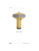
GR-5 Receiver
P/N 7010-1004
1-13
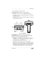
• Solid blue light – the Bluetooth module is on and a connection
has been established.
• No light – the Bluetooth module is off.
The Power button
turns the receiver on and off.
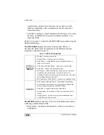
The FUNCTION button
switches the receiver between information
modes and post-processing modes, starts/stops data recording, and
changes the baud rate of the serial port to 9600. See “MINTER
Operation” on page 4-8 for more information. Table 1-2 on page 1-13
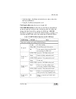
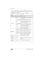
describes the REC LED status when using the FUNCTION button.
Table 1-2. FUNCTION Button Operations and REC LED Status
FUNCTION Key
REC LED
Status
When data recording is off, and the FUNCTION key is...
Not pressed
No light
No data recording.
Orange blink
Internal file system test in progress.
Red
No free memory; hardware problem with
data recording. No SDHC card.
Pressed for < 1
second
If FUNCTION key mode is “LED blink mode switch”
Orange
Release to change information mode.
If FUNCTION key mode is “Occupation mode switch”
Orange
No function.
Pressed for 1–5
seconds
If FUNCTION key mode is “LED blink mode switch”
Green
Release to start data recording (post-
processing occupation mode undefined).
If FUNCTION key mode is “Occupation mode switch”
Green
Release to start recording (Kinematic or
Static post-processing occupation mode).
Pressed for 5–8
seconds
Red
Release to turn serial port A baud rate to
9600 bps.
Summary of Contents for GR-5
Page 1: ... PERATORlS ANUAL ...
Page 2: ......
Page 4: ...ECO 4074 ...
Page 9: ...Table of Contents P N 7010 1004 v WEEE Directive C 2 Appendix D Warranty Terms D 1 Index ...
Page 10: ...Table of Contents GR 5 Operator s Manual Notes vi ...
Page 16: ...Preface GR 5 Operator s Manual Notes xii ...
Page 18: ...Introduction GR 5 Operator s Manual 1 2 Figure 1 1 GR 5 Receiver ...
Page 44: ...Introduction GR 5 Operator s Manual Notes 1 28 ...
Page 99: ...Configuring the Receiver Using TRU P N 7010 1004 3 27 Figure 3 24 Add New Message ...
Page 121: ...MINTER Configuration P N 7010 1004 3 49 Figure 3 42 MINTER Tab ...
Page 122: ...GR 5 Configuration GR 5 Operator s Manual 3 50 ...
Page 170: ...Troubleshooting GR 5 Operator s Manual Notes 6 12 ...
Page 188: ...GR 5 Operator s Manual Notes A 18 ...
Page 192: ...GR 5 Operator s Manual Notes B 4 ...
Page 196: ...GR 5 Operator s Manual Notes D 2 ...
Page 201: ......


