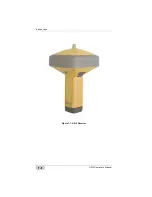
GR-5 Receiver
P/N 7010-1004
1-9
Once the signal is locked in the channel, it is demodulated and
necessary signal parameters (carrier and code phases) are measured.
Also, broadcast navigation data are retrieved from the navigation
frame.
After the receiver locks on to four or more satellites, its absolute
position in WGS-84 and the time offset between the receiver clock
and GPS time are computed. This information and the measurement
data can be stored in the optional SDHC card and downloaded later
onto a computer, then processed using a post-processing software
package. When the receiver operates in RTK mode, raw data
measurements can also be recorded into the receiver’s internal
memory. This allows the operator to double check real-time results
obtained in the field.
The GR-5 comes in one of the following configurations:
• with an FH915 Plus TX/RX/RP
1
radio modem
• with an FH915 Plus TX/RX/RP radio modem and a GSM/GPRS
module
• with a Digital radio modem
• with a Digital radio modem and GSM/GPRS or CDMA module
(for US customers)
• with a Satel radio modem and a GSM/GPRS module
Depending on your options, capabilities of the receiver include:
• Multipath reduction
• Satellite based augmentation systems (WAAS, EGNOS, and so
forth).
• Adjustable phase locked loop (PLL) and delay lock loop (DLL)
parameters
• Configurable internal long-range radio for DGPS and RTK
communications as well as Network based DGPS and RTK
solutions
• Automatic data logging
1. RP = repeater
Summary of Contents for GR-5
Page 1: ... PERATORlS ANUAL ...
Page 2: ......
Page 4: ...ECO 4074 ...
Page 9: ...Table of Contents P N 7010 1004 v WEEE Directive C 2 Appendix D Warranty Terms D 1 Index ...
Page 10: ...Table of Contents GR 5 Operator s Manual Notes vi ...
Page 16: ...Preface GR 5 Operator s Manual Notes xii ...
Page 18: ...Introduction GR 5 Operator s Manual 1 2 Figure 1 1 GR 5 Receiver ...
Page 44: ...Introduction GR 5 Operator s Manual Notes 1 28 ...
Page 99: ...Configuring the Receiver Using TRU P N 7010 1004 3 27 Figure 3 24 Add New Message ...
Page 121: ...MINTER Configuration P N 7010 1004 3 49 Figure 3 42 MINTER Tab ...
Page 122: ...GR 5 Configuration GR 5 Operator s Manual 3 50 ...
Page 170: ...Troubleshooting GR 5 Operator s Manual Notes 6 12 ...
Page 188: ...GR 5 Operator s Manual Notes A 18 ...
Page 192: ...GR 5 Operator s Manual Notes B 4 ...
Page 196: ...GR 5 Operator s Manual Notes D 2 ...
Page 201: ......


