


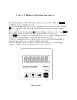
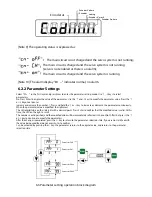


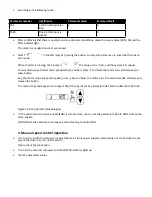
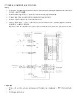

Select "dP- in layer 1" " and press Enter to enter the monitoring mode. There are 21
display states, users
Use the , keys to select the desired display mode, and then press the Enter key to
enter the specific display state.
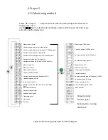
Figure 6.4 Output terminal display (stroke light is ON, OFF is OFF)
[Note 1]
The input pulse amount is a pulse amplified by the input
elec tronic gear.
[Note 2]
The pulse unit is the inter nal pulse unit of the system,
which is 10000 pulses/rev in this system. The pulse
amount is 5 digits high
+low 5 digits indicate that the calculation method is:
Pulse amount = high 5 digits x low 5 digits
[Note 3] Control mode: 0-position control; 1-speed control; 2-speed test run; 3-JOG operation;
4-encoder adjustment
Zero; 5-open loop operation.
[Note 4] If the display number reaches 6 digits (if -12345 is displayed), the prompt character is
no longer displayed.
[Note 5] The position command pulse frequency is the actual pulse frequency before the input
electronic gear is amplified, the minimum unit
At 0.1 kHz, the forward direction shows a positive number and the reverse direction
shows a negative number.
[Note 6] Indicates the effective value of the phase current. The calculation method of the
current I is:
[Note 7] The absolute position of the rotor in one revolution indicates the position of the rotor
relative to the stator in one revolution, with one revolution for one week.
Period, the range is 0 ~ 9999, this value is independent of the electronic gear ratio.
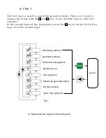
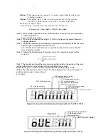
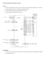
[Note 8] The input terminal is shown in Figure 6.3, the output terminal is shown in Figure 6.4,
and the encoder signal is shown in Figure
6.5 is shown.
INH (command pulse inhibit)
SC2 (speed selection 2)
CLE (deviation counter clear)
SC1 (speed selection 1)
ZEROSPD (zero speed clamp)
RSTP (CW drive disabled)
FSTP (CCW driver disabled)
ALRS (alarm clear)
SON (servo enable)
FIL (CCW Torque Limit)
RIL (CW torque limit)
Figure 6.3 Input terminal display (stroke light is ON, OFF is OFF)
Reserved
Co IN (positioning completed)
SCMP (speed arrival)
ALM (servo alarm)
SRDY (servo ready)
Summary of Contents for SD300
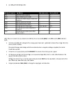
Page 87: ......
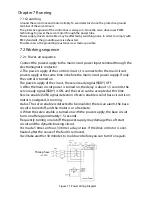
Page 89: ...Chapter 7 Running 7 9 2 Operation l Set the parameter values ...


