


Chapter 3
Interface
Controller
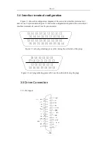
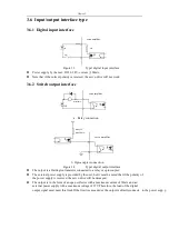
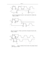
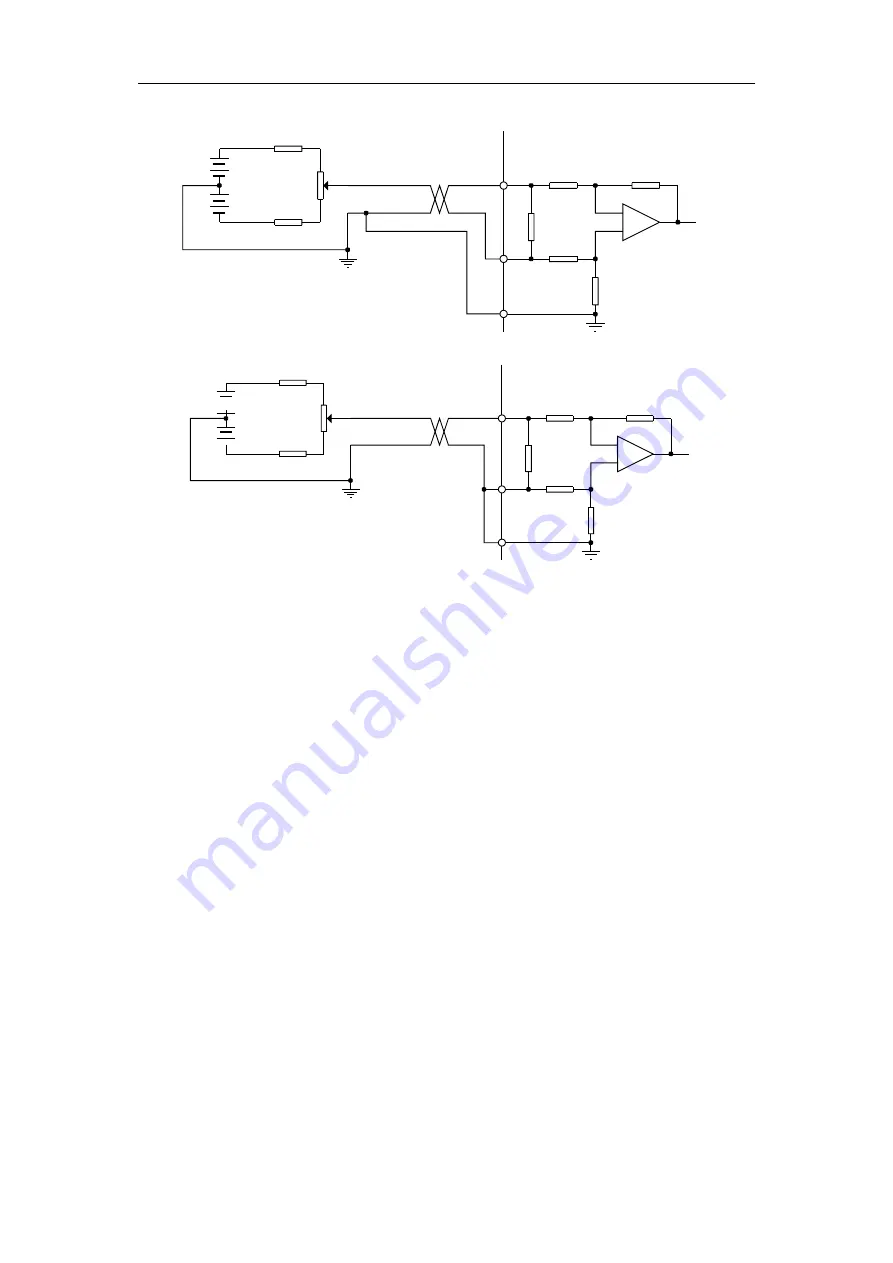
Figure 3.10 c Analog Differential Potentiometer Input Interface (type4)
Controller
R
200(1/2W)
servoamplifier
12V
AS+ orAT+
VR
2K(1/2W)
12V
R
200(1/2W)
10k
-
+
AGND
AS- or AT-
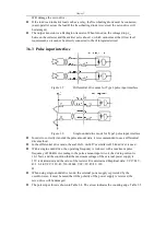
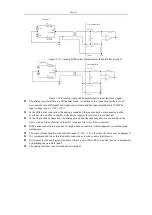
Figure 3.10 d Analog single-ended potentiometer input interface (type4)
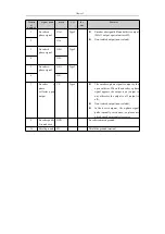
The analog input interface is a differential mode. According to the connection method, it can
be connected into differential and single-ended forms, and the input impedance is 10kΩ.The
input voltage range is -10V~+10V;
In the differential connection, the analog ground and the input negative are connected on the
controller side, and the controller to the driver requires three wires to be connected;
In the single-ended connection, the analog ground and the input negative are connected on the
driver side, and the controller to the driver requires two wires to be connected;
Differential connection is superior to single-ended connection, which suppresses common mode
interference;
The input voltage should not exceed the range of -10v~+10v, otherwise the drive may be damaged.
It is recommended to use shielded cable connections to reduce noise interference;
It is normal for the analog input interface to have a zero offset. The zero offset can be compensated
by adjusting the parameter pa45.
The analog interface is non-isolated (non-isolated).
R
200(1/2W)
servo amplifier
12V
AS+ orAT+
VR
2K(1/2W)
12V
R
200(1/2W)
10k
-
+
AGND
AS- or AT-
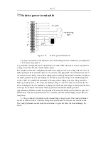
Summary of Contents for SD300
Page 87: ......
Page 89: ...Chapter 7 Running 7 9 2 Operation l Set the parameter values ...


