Top Notch Products Mooney M-18 Assembly Manual Download Page 7

£ 

8

6

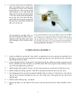
Locate ESMR and ESM. Use three #1 

x 3/16” stainless flat head wood screws 

to  attach  ESMR  to  ESM.  Screw  one 

ESMR  to  each  end  of  ESM.  Test  fit 

and then glue this assembly to S2-BOT 

and  S3-BOT  in  the  notchs  supplied. 

Take  care  not  to  get  adhesive  on  the 

ply plate ESM. After the adhesive has 

set, remove the screws and ESM. This 

method  will  assure  that  ESM  will  fit 

perfectly after sheeting.

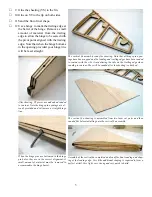
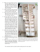
Partially assembled stabilizer section with only the bottom sheeting remain

-

ing to be added. All components are clearly visible here. Note the servo 

mounting screw rails between S2-BOT and S3-BOT, the hinge point caps, 

and leading and trailing edges.

£ 

9

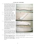
The  stabilizer  sheeting  is  labeled  SS 

with a T or a B for top or bottom. The 

bottom sheeting has holes cut into it for 

the servo plates and the servo wire exit 

holes. Assemble two top and two bot-

tom sheets. They are comprised of three 

sections each.

£ 

10

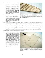
Sand the leading and trailing edge of the stabilizer assembly to contour with the ribs,. This should only 

require a few passes with sandpaper. Test fit one of the top sheet assemblies. Assure that it lines up with 

the center rib and the tip rib. Then remove it. Apply a bead of thick CA along the trailing edge and the 

install the sheeting by inserting the notches in the sheeting into the tabs in STE. Turn the assembly and 

while holding each rib firmly against the rib, apply thin CA. Do the aft half of each rib first, then turn the 

assembly around and complete the forward portion of the ribs. Then while holding the leading edge sheet-

ing against SLE, trickle CA down the inside of the assembly to glue the sheeting at the leading edge.

£ 

11Repeat this operation for the remaining top sheeting.

£ 

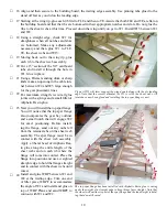
12 To install the bottom sheeting, use ali-

phatic resin glue along each rib with the 

exception of the area around the servo 

bay opening. We will be trimming this 

material later and will glue it after trim-

ming. Put a bead of thick CA along the 

trailing  edge  STE  and  then  place  the 

sheeting  into  the  tabs  on  STE.  Hold 

this assembly flat until the trailing edge 

glue has cured. Pull the sheeting tight 

and firmly squeeze it at the leading edge 

while applying thin CA. Work your way 

along the leading edge until complete. 

Repeat  this  method  for  the  remaining 

bottom sheeting.

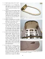
ESM is temporarily installed and used as a guide to cut the exact opening 

for it. Note the counter sink on ESM so the screw heads will sit flush with 

the surface.

Summary of Contents for Mooney M-18

Page 1: ...TOP NOTCH Mooney M 18 Mooney Mite ASSEMBLY MANUAL Top Notch Products Company PO Box 1051 Goodlettsville TN 37072 Made in the USA...

Page 2: ...ave to do this No mention of this is made on the package they come in PIN REGISTRATION Agreat shop technique introduced by Top Notch Products is the use of 1 8 piano wire pins to quickly and precisely...

Page 3: ...nd that can be confusing while in the building process 2 Install V1 into the appropriate notches in the core sheet VC Observe the cor rect size notches the narrower end is the leading edge Hold V1 fir...

Page 4: ...barrel of the hinge Remove a small amount of material from the trailing edge to allow the hinge to be seated with the pivot point aligned with the trailing edge Note that when the hinge bottoms in the...

Page 5: ...d into contact with the assembly Re move from the pins and put under pres sure until cured 3 The leading edge of the rudder assem bly will need to be double beveled to accommodate the swing of the rud...

Page 6: ...stallation of this assembly will be done after installing on the aircraft and fin ishing STABILIZER ASSEMBLY Locate the stabilizer core sheet SC Note that SC is supplied in two sections and must be a...

Page 7: ...center rib and the tip rib Then remove it Apply a bead of thick CA along the trailing edge and the install the sheeting by inserting the notches in the sheeting into the tabs in STE Turn the assembly...

Page 8: ...r now assemble the larger EC and ES B using the pin register method First a ES B then a EC and then an other ES B The finished servo installation Note that you will need a servo reversing Y Connector...

Page 9: ...parts before the assembly becomes ridged and inflexible Please follow gluing instructions and do not glue the assembly until instructed to do so I cannot over emphasize the importance of having all pa...

Page 10: ...nd then return to the center and finish the other end 13 Locate TE A TE B and TE C The trailing edge is comprised of an assembly of these three piec es See the plan for the stack order Use a single pi...

Page 11: ...upport the wing dowels along with the ply leading edge Note that the correct dihedral for W1 is set by the sheer webs All joints have now been glued and installing the top spar flange is next 10 The t...

Page 12: ...ntersink the screw holes for the flat head screws They will sit flush to the surface when finished The easiest way to assure that everything will line up when finished is to temporarily attach The fla...

Page 13: ...he spar flange wheel well out liner 34 The wing is now ready for sheeting You can prepare the sheeting to the dia gram on the plans for best results Sand the outside of the sheeting prior to in stalli...

Page 14: ...The wing jigs for installing the bottom sheeting They will support the wing assembly and prevent changes in wash out during the sheeting procedures 39 The landing gear mount LGP is lami nated from two...

Page 15: ...e just cut After cleaning up any remain ing material and after you are satisfied with the fit glue the inside edges of the sheeting around the servo opening 44 Glue on the outer leading edge use pins...

Page 16: ...in the top and bottom spar flanges When installed the wing spar will be one contiguous I beam from tip to tip Remove the 1 16 balsa sheeting at the root Use WJ as a template Apply Epoxy to the top spa...

Page 17: ...asi est way to shape the flaps See the plans for the correct angles to set the saw If not use your plane and sandpaper to shape the flaps Remove a small amount of material from FL 1 and FL 3 at the hi...

Page 18: ...embly showing the core sheet leading edge A 1 rib and sheeting Very light and very strong 6 Install and glue AHPF 7 Turn the assembly over and install A1 BOT through A5 BOT 8 Install ALE BOT 9 Install...

Page 19: ...te firewall sec tions The firewall is laminated from two 1 8 ply sections lite ply for the electric version and aircraft ply for the glow version Use pin registry and glue the two firewall layers toge...

Page 20: ...all at this time 14 After curing use Epoxy to form the sides to the firewall Glue in the balsa gussets FG as necessary above and below F9 Saturate these with thin CA for additional strength 15 Locate...

Page 21: ...of these into there re spective notches in F2 and the firewall F3 sub assembly with the wing bolt plate and bracing attached an ready to be installed Bracing for the firewall is supplied by gussets b...

Page 22: ...top sheeting Once again you will want to soak these parts prior to bend ing them around the firewall and F2 29 Install seven 3 16 x 3 16 square balsa stringers into the notches provided in F3 through...

Page 23: ...Install and glue F4 B 37 If you haven t already done so sand the sheeting you applied to the tail section when you pinched it together flush with the bottom of the fuselage sides You will install the...

Page 24: ...lied to remove any guesswork regarding the position of the fuselage When the leveling stand is installed into the wing dowel holes in F2 and a 3 3 4 block is placed under F7 the fuselage is level This...

Page 25: ...ount of filler required to get a smooth transition with the fin 4 Glue the dorsal fin assembly onto the vertical fin and fuselage Much of the strength of the attachment of the stabilizer and vertical...

Page 26: ...owl on the bench and using a Sharpie draw a line 3 16 above the bench top all the way around the cowl Trim the edge of the cowl at this line Temporarily place the cowl ring just inside the edge of the...

Page 27: ...for an almost invisible clean install with no screw or bolt heads protruding Aircraft Weight Wing Loading Lbs Oz Oz Per Sq Ft 9 0 22 99 9 4 23 63 9 8 24 27 9 12 24 90 10 0 25 54 10 4 26 18 10 8 26 82...

Page 28: ...6 X 35 F10 5 LPLY 1 8 X 12 X 26 F10 X2 5 LPLY 1 8 X 12 X 26 F2 8 AC PLY 1 8 X 12 X 35 F2 A 8 AC PLY 1 8 X 12 X 35 F3 8 AC PLY 1 8 X 12 X 35 F4 8 AC PLY 1 8 X 12 X 35 F4 B 38 BALSA 1 4 X 3 X 36 F5 5 LP...

Page 29: ...LSA 1 16 X 4 X 36 SS T 10 BALSA 1 16 X 4 X 36 SS T X4 11 BALSA 1 16 X 4 X 36 ST X4 34 BALSA 1 4 X 4 X 36 STE X4 33 BALSA 1 4 X 3 X 36 SV 18 BALSA 1 16 X 4 X 36 SV X3 12 BALSA 1 16 X 4 X 36 SW B 26 BAL...

Page 30: ...4 X 36 W9 X2 32 BALSA 3 32 X 3 X 36 WBP X2 4 AC PLY 1 16 X 12 X 48 WBPF X2 40 BALSA 1 4 X 3 X 36 WBPF X2 41 BALSA 1 4 X 3 X 36 WCO 7 AC PLY 1 64 X 6 X 24 WDP 8 AC PLY 1 8 X 12 X 35 WJ X6 39 BALSA 1 4...

Reviews: