


£
2
£
1
5
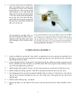
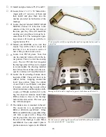
Locate the steering arm in the hardware
pack. The locking screw location must
be changed 90° so that it can be installed
through the side of the fuselage during
final assembly. To do this, press the
brass barrel out of the nylon horn. Drill
a 7/64” hole in the nylon hub parallel to
the steering arm. Then press the brass
barrel back into the nylon arm aligning
the screw hole in the barrel with the new
hole in the nylon arm.
A nose wheel steering arm is used on the rudder but it has to be modified
as shown above. The brass hub is removed from the Nylon arm and a 7/64”
hole is drilled into it in alignment with the arm. The hub is then installed
with the locking bolt hole in alignment with it. A #4-40 x 1/4” socket head
bolt will replace the regular screw. The steering arm in the background is
the stock configuration. This will facilitate installing it through the side of
the fuselage during final installation.
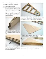
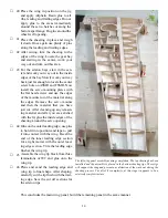
This concludes the assembly of the ver-
tical fin and rudder assembly. Final in
-
stallation of this assembly will be done
after installing on the aircraft and fin
-
ishing.
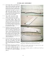
STABILIZER ASSEMBLY
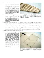
Locate the stabilizer core sheet SC. Note that SC is supplied in two sections and must be assembled. Note
that there is a small web between the sides of the hinge opening at the root end. Remove this web before
proceeding with the assembly.
£
2 Locate and prepare all ribs, S1 through S7. Note that S2 and S3 have different geometry on the bottom for
the servo mount screw rails. Be sure to use S2-TOP and S3-TOP on the top side of the stabilizer. Assume
you will be assembling the top side first.
£
3
Install and glue all top side rib sections. Use the same technique as you did on the vertical fin section.
£
4 Install and glue the trailing edge STE. Note that it must align with the notches in the core sheet.
£
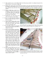
5 The leading edge SLE is quite thin and must be handled with care. Remove it from the sheet, clean off any
nubs left by the retainers and install onto the core sheet. Make sure it is flat against the core sheet before
applying glue.
£
6 Install and glue all hinge caps, (six places).
£
7 Flip the assembly over and install all rib sections. Note that ribs S2 and S3 are labeled S2-BOT and S3-
BOT.


